
Palatal expansion device and methods

a technology of a palatal expansion device and a palatal arch, which is applied in the field of palatal expansion device and methods, can solve the problems of difficult to find, difficult to find, and often a significant maxillary arch

Inactive Publication Date: 2007-09-20
KELES AHMET OZLEM
View PDF15 Cites 36 Cited by
  • Summary
  • Abstract
  • Description
  • Claims
  • Application Information

AI Technical Summary

Benefits of technology

[0013] The present invention has several advantages. The device does not require a pin shaped key for activation of the screw because an activation arm is built-in into the device. The device of the present invention is safer because there is no risk of swallowing a pin shaped key or puncturing the soft palate during insertion of such a key. The built-in activation arm more easily allows for activation of the screw and is therefore more patient friendly. As such, greater patient compliance is obtained. Another advantage of the present invention is the built-in locking or ratchet (e.g., anti-wind-back) mechanism which prevents the screw from winding back after the desired expansion is achieved.

Problems solved by technology

Constricted maxillary arch is often a significant dental and skeletal problem in field of orthodontics.
Looking at the above-described device from a clinical point of view, patients have a hard time finding the hole on the screw with the pin shaped key, inserting the key and turning the screw backwards in the direction of the throat by looking to an inverted image on a mirror.
Hence, even with the help of the pin shaped key, it is difficult to find.
Furthermore, other risks exist.
They include injuring the soft palate during insertion of the key and / or swallowing the key during activation.
In some cases, accidental swallowing of orthodontic expansion appliance keys has been reported.
However during this time period, unwinding of the screw can happen thereby causing the blocks to retract, and some of the achieved expansion can be lost during the stabilization period.

Method used


Image

  • Palatal expansion device and methods
  • Palatal expansion device and methods
  • Palatal expansion device and methods

Examples


Embodiment Construction

[0047] A description of preferred embodiments of the invention follows.

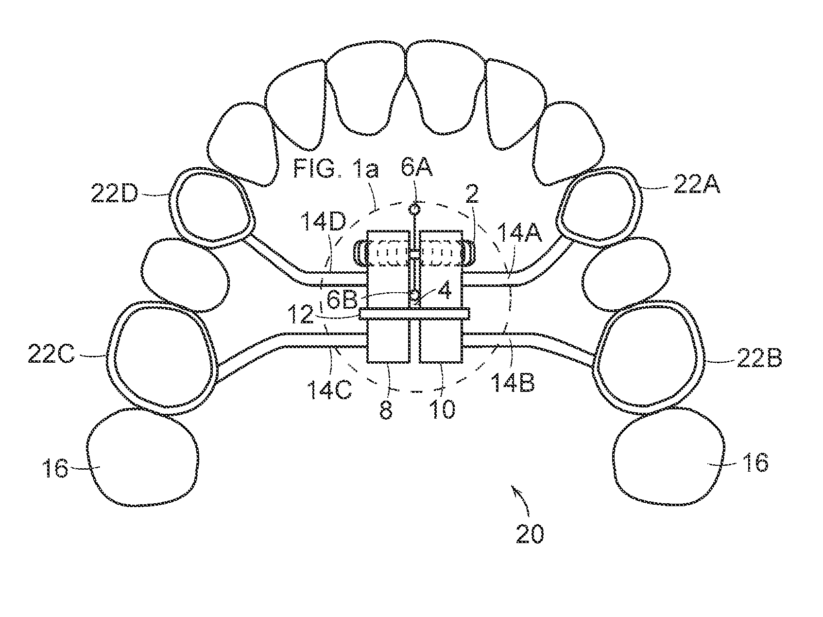
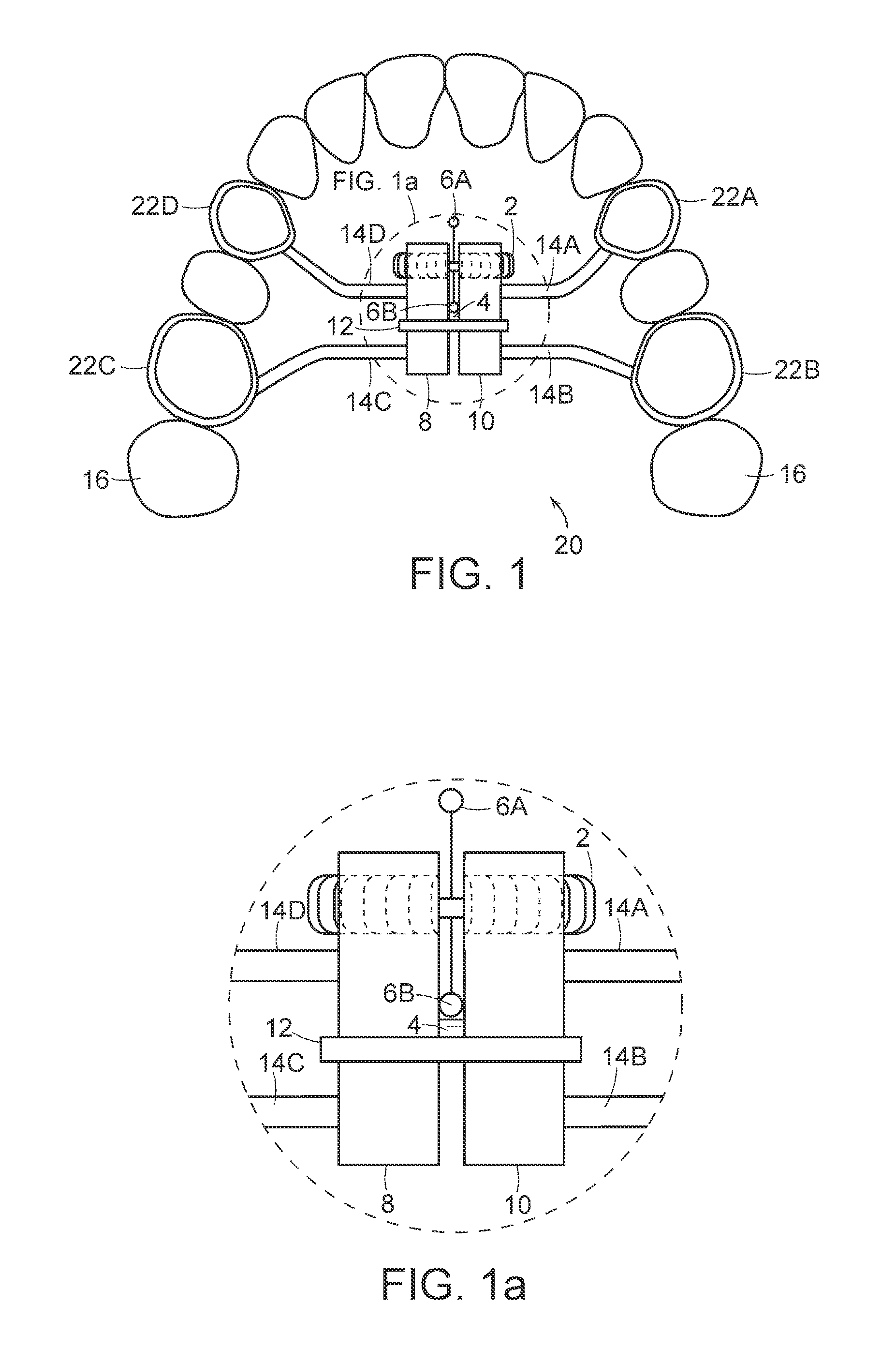
[0048] Referring to FIG. 1, palatal expansion device 20 is secured to maxillary arch 16 by bands 22A-22D and retaining wires 14A-14D. Palatal expansion device 20 has a mid-palatal screw 2 that separates blocks 8 and 10 to expand the upper jaw and dentition. In this embodiment, screw 2 has four prong-shaped activation arms, activation arms 6A-6D, that are securely attached to a middle portion of screw 2. A detailed view of screw 2 and activation arms 6A-6D are shown in this figure and in FIG. 3D. In addition to a screw, other means for separating the block can be use so long as the means is attached to an activation arm that can be engaged by the user and acts to separate the blocks, as described herein. Additionally, a combination of one or more screws can be used in place of a single screw. For example, two screws opposing each other can be used to push the blocks outward, connected by a metal connector to whic...


PUM


Abstract

The present invention relates to a palatal expansion device that has a screw having an activator (e.g., one or more activation arms) wherein the screw connects two blocks, each block having an opening for receiving the screw; a stabilizer attached to the blocks; and an anti-wind-back mechanism (e.g., a spring extension) positioned opposite the activation mechanism. In another embodiment, the present invention includes a palatal expansion device that has at least one screw, wherein the screw connects with one or more blocks and the blocks have an opening for receiving the screw. The device further includes one or more stabilizers attached to the blocks; a ratchet that engages the screw; and a built-in activator that communicates with the ratchet. This design allows essentially unidirectional rotation of the screw. The ratchet system includes, in one aspect, a pin / pocket arrangement, or a ratchet wheel / spring arrangement. The present invention involves kits and methods for expanding the maxillary arch or mandible using the palatal expansion devices of the present invention.

Description

RELATED APPLICATIONS [0001] This application is a Continuation-In-Part of International Application No. PCT / US2006 / 018562, entitled, “Palatal Expansion Device and Methods,” by Ahmet O. Keles which designated the United States and was filed May 15, 2006, published in English; which is a continuation-in-part of U.S. patent application Ser. No. 10 / 908,536, filed May 16, 2005, now issued as U.S. Pat. No. 7,074,036, entitled, “Palatal Expansion Device and Methods”, by Ahmet O. Keles. [0002] The entire teachings of the above applications are incorporated herein by reference.BACKGROUND OF THE INVENTION [0003] Constricted maxillary arch is often a significant dental and skeletal problem in field of orthodontics. Prior to the present invention, a fixed palatal expansion device generally consisted of a 4-band device with a midpalatal screw. In this example, the appliance had fixed bands on the maxillary first permanent molars and first premolars, connected on each side by a rigid bar, with bo...

Claims


Application Information

Patent Timeline
IPC IPC(8): A61C7/00
CPCA61C7/10
Inventor KELES, AHMET OZLEM
Owner KELES AHMET OZLEM
Learn More