
Pattern matching system and targeted object pursuit system

a matching system and target object technology, applied in the field of pattern matching system and target object pursuit system, can solve the problems of increasing the size requirement, in bits, digital arithmetical unit necessary, and not always fully using the capacity of digital arithmetical uni

Inactive Publication Date: 2007-09-20
RICOH IMAGING COMPANY
View PDF10 Cites 7 Cited by
  • Summary
  • Abstract
  • Description
  • Claims
  • Application Information

AI Technical Summary

Benefits of technology

[0007]Therefore, an object of the present invention is to provide a pattern matching system that uses a digital arithmetical unit effectively, and a targeted object pursuit system that makes use of the pattern matching system.

Problems solved by technology

However, the greater the number of compared image components also increases the size requirement, in bits, of the digital arithmetical unit necessary for the pattern matching system.
On the other hand, even though a higher bit digital arithmetical unit is mounted, the capacity of the digital arithmetical unit is not always used completely.

Method used


Image

  • Pattern matching system and targeted object pursuit system
  • Pattern matching system and targeted object pursuit system
  • Pattern matching system and targeted object pursuit system

Examples


Embodiment Construction

[0032]The present invention is described below with reference to the embodiment shown in the drawings.

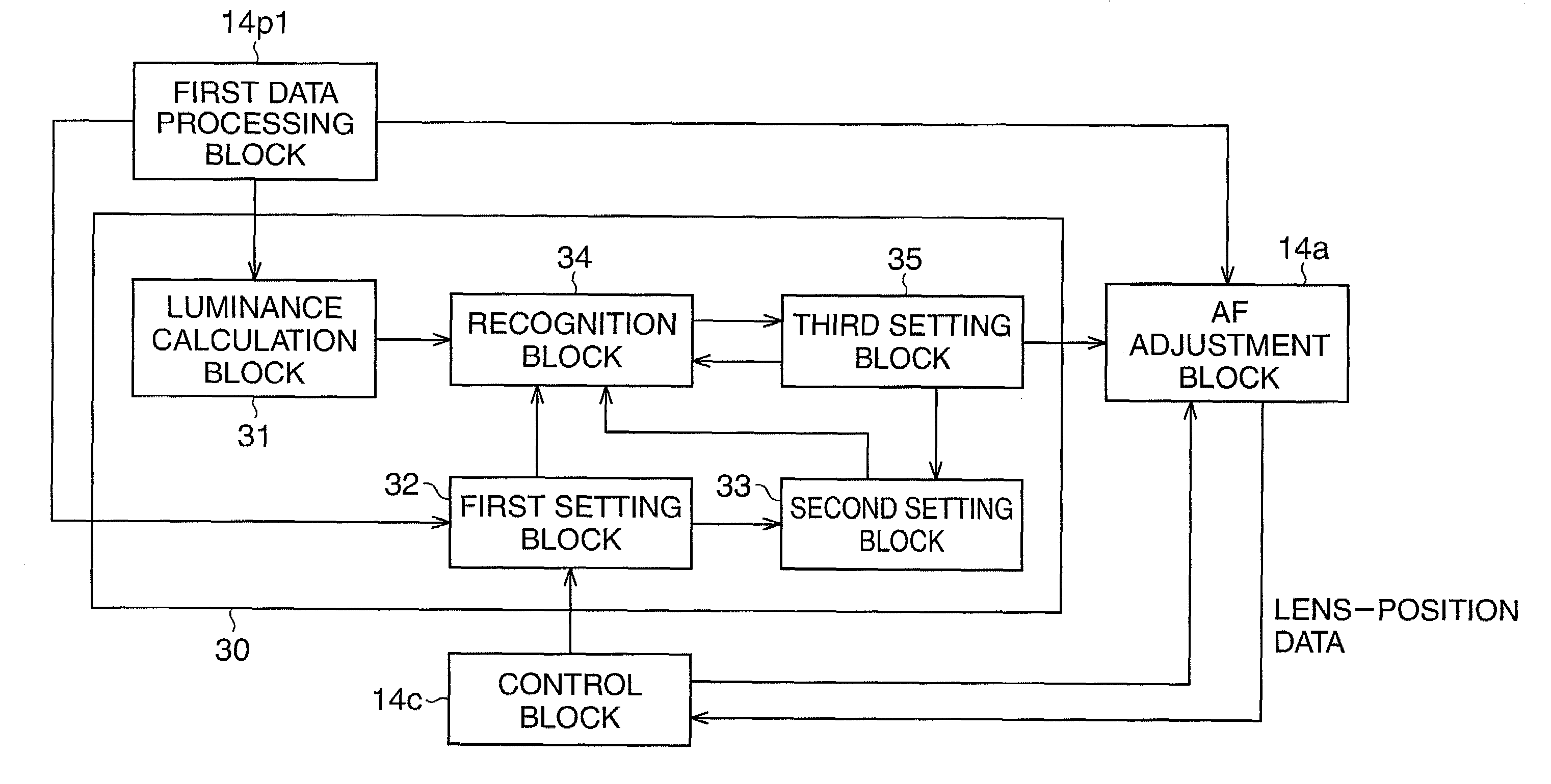
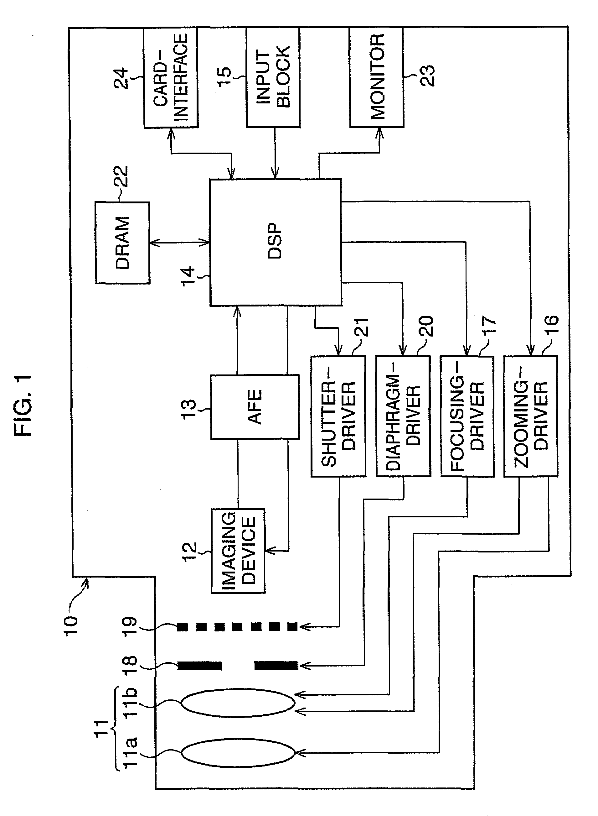
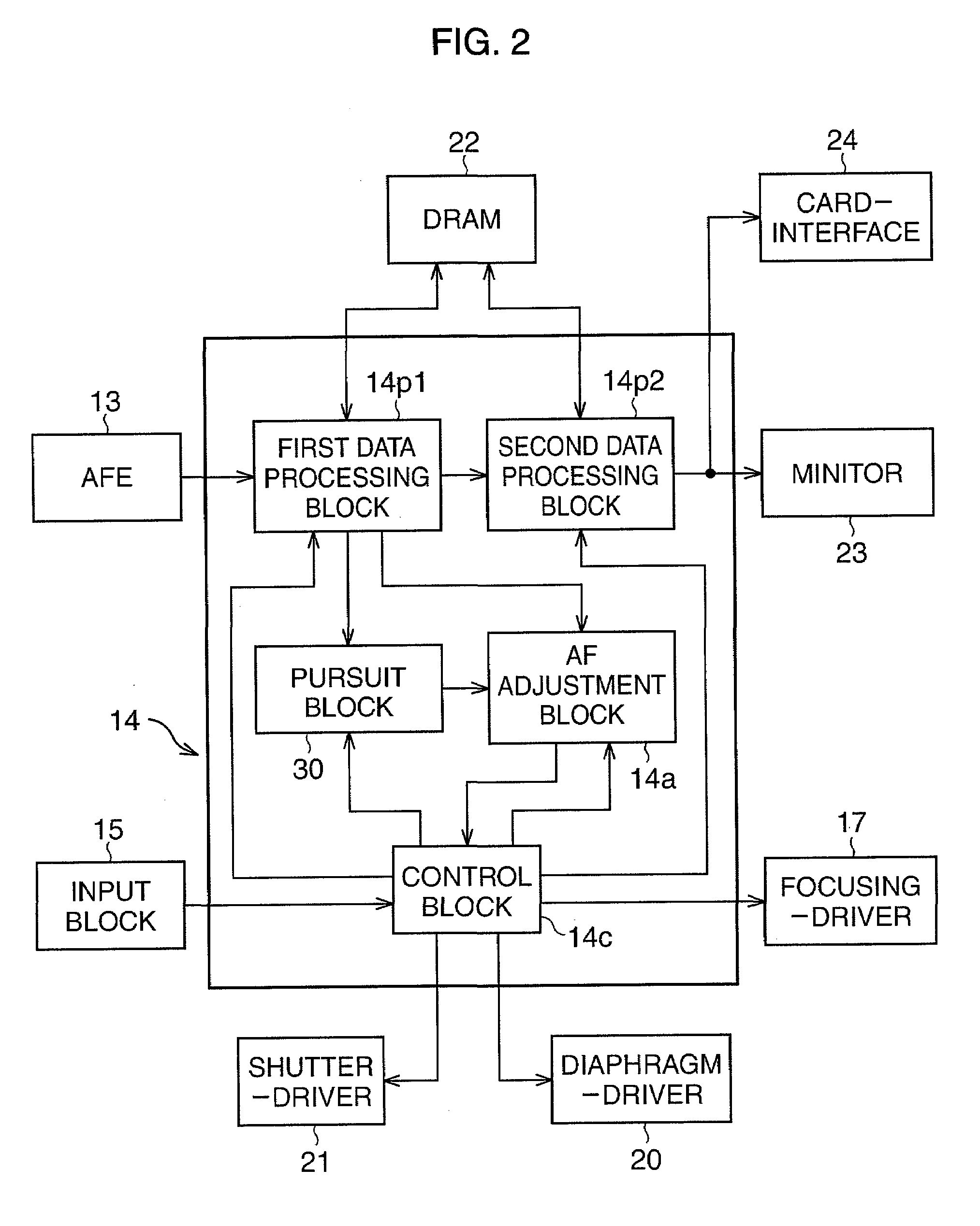
[0033]In FIG. 1, a digital camera 10 comprises a photographic optical system 11, an imaging device 12, an analog front end (AFE) 13, a DSP 14, an input block 15, a zooming-driver 16, a focusing-driver 17, and other components.

[0034]The photographic optical system 11 is optically connected to the imaging device 12. An optical image of an object through the photographic optical system 11 is incident to the light-receiving surface of the imaging device 12. The imaging device 12 is, for example, a CCD area sensor. When the imaging device 12 captures the optical image of the object upon its light-receiving surface, the imaging device 12 generates an image signal corresponding to the captured optical image.

[0035]The photographic optical system 11 comprises plural lenses, including a zoom lens 11a and a focus lens 11b. The zoom lens 11a and the focus lens 11b are movable along an optical a...


PUM


Abstract

A pattern matching system that outputs an likeness values, comprising a designation block, a comparison block, a calculation block and an output block, is provided. The likeness value shows how much a first and second image compares to each other. The designation block designates a first and second image data as data to be compared. The first and second image data comprises 2̂x of area data. The comparison block compares the data level of the area data corresponding to pattern areas at the relatively same location in the first and second images. The calculation block calculates the likeness value. The likeness value varies according to the number of the pattern areas where the absolute value of the difference between the compared data levels of the area data is less than a predetermined standard value.

Description

BACKGROUND OF THE INVENTION[0001]1. Field of the Invention[0002]The present invention relates to a pattern matching system that determines whether or not a plurality of images matches each other, and a targeted object pursuit system that pursues the movement of a specified targeted object within a plurality of images captured sequentially using the above pattern matching system.[0003]2. Description of the Related Art[0004]A pattern matching system that calculates the likeness between a plurality of images is known. The pattern matching is used for pursuit of a targeted object moving within a plurality of images captured sequentially.[0005]In prior pattern matching, the likeness is calculated by the following operation. First, the captured image is divided into smaller image components and the luminance of the divided image components is detected. Second, the luminance level of each image component into which a first image is divided is compared to that of a corresponding image compo...

Claims


Application Information

Patent Timeline
Patent Type & Authority Applications(United States)
IPC IPC(8): G06K9/68
CPCH04N5/23212G06T7/2013G06T7/223
Inventor YAMAMOTO, YASUHIRO
Owner RICOH IMAGING COMPANY
Learn More