Integrated large XY rotary positioning table with virtual center of rotation

Inactive Publication Date: 2007-09-20
EIDELBERG BOAZ
View PDF24 Cites 22 Cited by
  • Summary
  • Abstract
  • Description
  • Claims
  • Application Information

AI Technical Summary

Benefits of technology

[0019]It is still another object of the present invention to provide a X, Y, ⊖ positioning system with a virtual center of rotation for large format machines that use low cost structures.
[0020]It is another object of the present invention to provide a X, Y, ⊖ position system with virtual center of rotation for large format machines that use low cost bearings.
[0021]It is yet another object of the present invention to provide a X, Y, ⊖ positioning system with a virtual center of rotation for large format machines that has the ability to simultaneously correct for position errors in the XY direction of motion of large moving substrates including straightness and yaw errors for both the X and Y axes.
[0022]It is still another object of the present invention to provide a X, Y, ⊖ positioning system that can obtain an optimal virtual center of rotation to align a substrate.
[0025]The present positioning system allows the user to position large format glass substrates and the like with precision control. Specifically, depending on the mounting configuration of the present invention the user may correct for straightness in X, X′ and Y directions, yaw in the ⊖ rotation direction and position in the X, X′ and Y direction. As shown by the mathematical formulation of this invention in the Appendix, any one axis of the three degrees of freedom slide motion X, Y, ⊖ (Rotary) can be therefore corrected in either machine base fixed XY coordinate system or in moving X′Y′ coordinated system, fixed to the moving Substrate slide. This is achieved via a positioning system that implements at least one motor and encoder for the Y slide and for the two cross stages X1, X2.

Problems solved by technology

Compounded stages consume larger height and typically result in lower precision due to larger Abbe offset.

Method used


Image

  • Integrated large XY rotary positioning table with virtual center of rotation
  • Integrated large XY rotary positioning table with virtual center of rotation
  • Integrated large XY rotary positioning table with virtual center of rotation

Examples


Embodiment Construction

[0050]As required, detailed embodiments of the present invention are disclosed herein; however, it is to be understood that the disclosed embodiments are merely exemplary of the invention, which may be embodied in various forms Therefore, specific structural and functional details disclosed herein are not to be interpreted as limiting, but merely as a basis for the claims and as a representative basis for teaching one skilled in the art to variously employ the present invention in virtually any appropriately detailed structure.

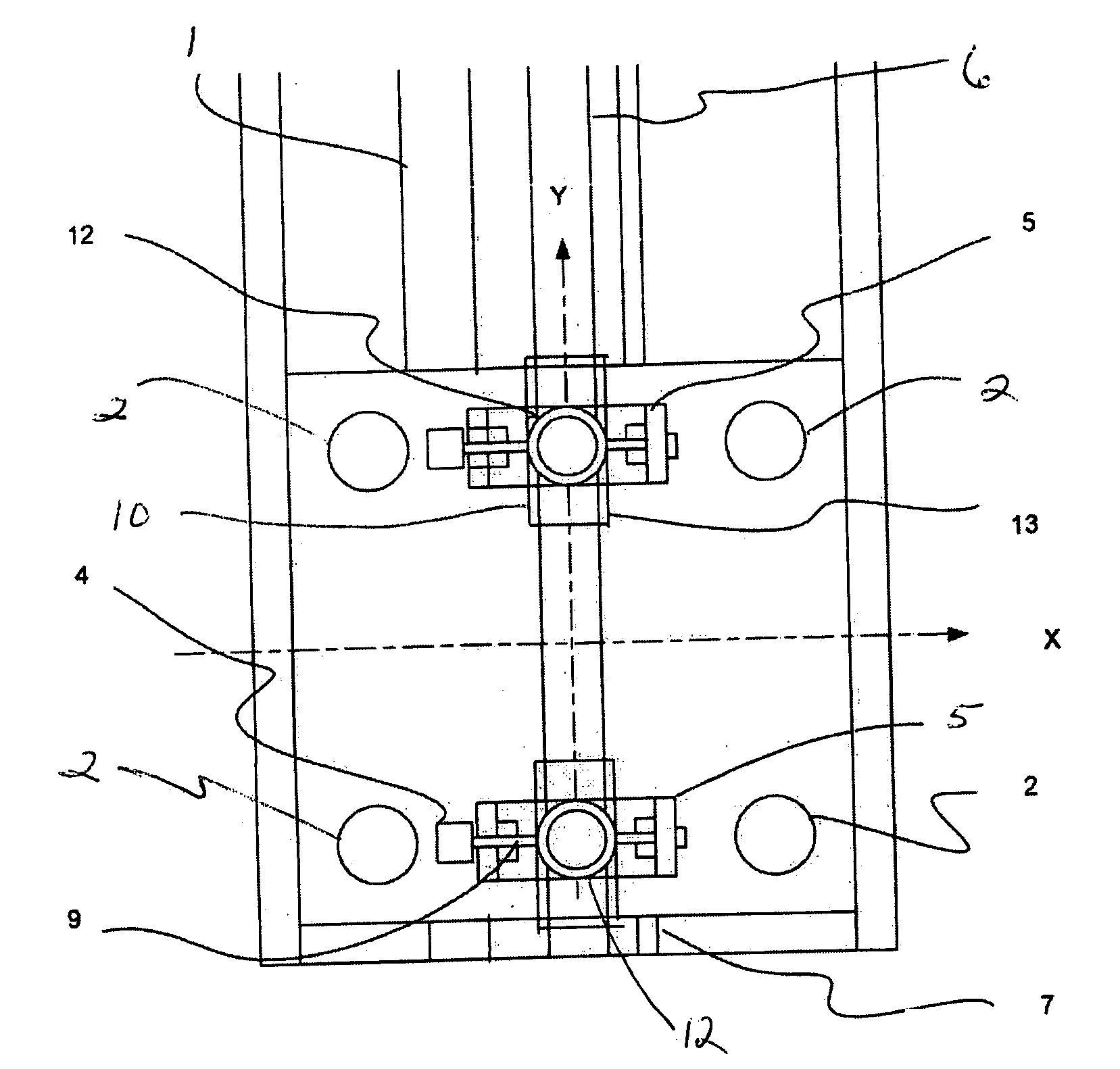
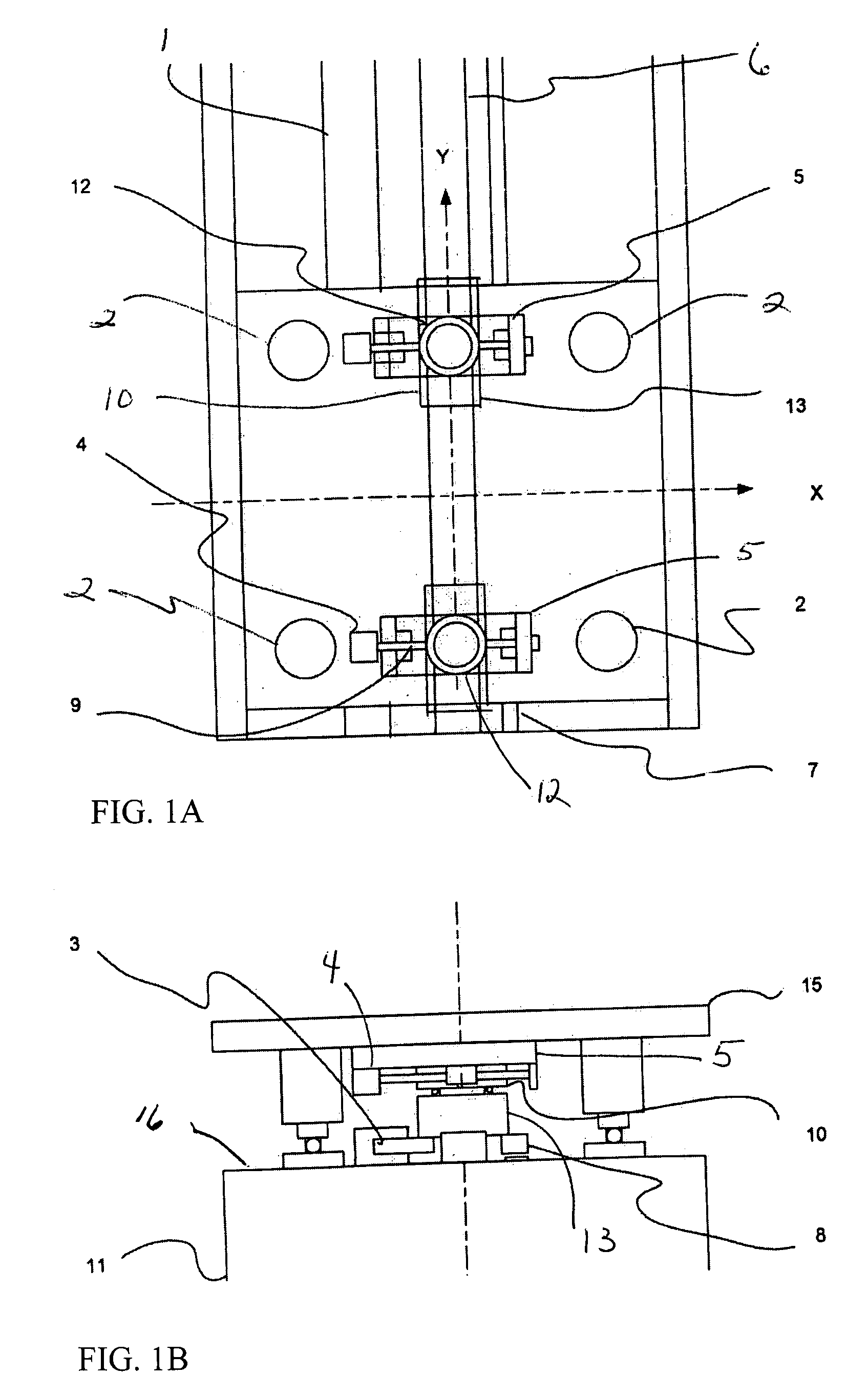
[0051]Drawing one's attention to FIGS. 1a and 1b one embodiment of the positioning system of the present invention is shown. The system of this embodiment may include a generally flat surface 16 on a base 11 on which the machine substrate slides. Plate 15, is free to move in a X axis and a Y axis and rotate in the ⊖ direction while being supported by at least one air bearing puck 2. Base 11 may be constructed of any suitable material known in the art including...


PUM


Abstract

The present invention allows for a large format substrate plate to move precisely in X, Y and ⊖ Rotary directions with an integrated linear XY mechanism. The mechanism includes X1, X2 stages which are mounted to the moving substrate plate and Y1 and Y2 stages which are mounted to the machine base. The slides of the X and Y stages are connected to each other through a revolute joint. The resulting integrated X,Y mechanism can move the substrate plate in X,Y and Rotary ⊖ directions preferably by motorizing at least three of the four linear stages with feedback encoders and by using computer controller to command the three motorized stages to move to their desired positions. The relationship between the desired position of the substrate in a global XY coordinate system and the motion of each motorized stage is provided through trigonometric transformations which are integral part of this invention. This configuration can also be used to correct translation and rotational positioning errors of the substrate plate using straightness and yaw maps. The mechanism of the present invention may be used to precisely position large format glass substrates in position systems for large substrate process tools. The positioning system includes a base assembly, on which the integrated XY mechanism is mounted. The moving substrate slide may be supported on the base assembly by air bearing pucks or by recirculating rail pucks. Motion in the Y direction may be provided by linear motor coil mounted to at least one of the Y pucks with a magnet mounted to the base surface in Y direction. Motion in the X direction is achieved by one or two X slides mounted to the moving plate which support the substrate in a configuration which includes, two motorized cross stages slides X1 and X2 with encoders which are connected to the Y1 Y2 slides respectively by a unique revolute joint Motion in the ⊖ direction can be achieved by opposite motion of either X1 and X2 stages or Y1 and Y2 stages or in a special double gantry configuration by all four stages where only three axes are independent.The present invention allows multiple mounting configurations of the X, Y stages which allows the user to control very large format substrates in an economic way using standard X,Y stages and low cost structural and sensing components. In addition the present invention allows the user to achieve extreme precision positioning as may be needed for process machines such as printing, laser scribing, machining, inspection and biotechnology assaying of large substrate plates by commanding the motorized stages of the mechanism to move to target position using error mapping and the kinematic formulations of this invention

Description

[0001]The present application claims priority on U.S. Provisional Patent Application Ser. No. 60 / 784,048 filed Mar. 20, 2006, the disclosures of which are incorporated herein by referenceFIELD OF INVENTION [0002]The present invention relates to a positioning system, which may be used with for example, large flat substrates, including but not limited to large format glass substrates. The large format glass substrates included in the present invention are typically used in applications associated with printing, scribing and inspecting solar panels and flat panel displays. In addition the present invention may be used for semiconductor production and various other automation applications which require X, Y ⊖ (Rotary) positioning systems.BACKGROUND OF THE INVENTION [0003]The present invention is a unique positioning system that may be used with many processes that require precision X,Y, ⊖ movement, i.e. stage travels, in the range of up to X 1,000 millimeters, Y 5000 millimeters and ⊖45...

Claims


Application Information

Patent Timeline
IPC IPC(8): G03B27/58
CPCG03B27/58
Inventor EIDELBERG, BOAZ
Owner EIDELBERG BOAZ
Why Eureka
Try Eureka