
Diecast machine and diecast method

Inactive Publication Date: 2007-09-20
NGK INSULATORS LTD +1
View PDF8 Cites 13 Cited by
  • Summary
  • Abstract
  • Description
  • Claims
  • Application Information

AI Technical Summary

Benefits of technology

[0014] An object of the present invention is to provide a diecast machine and a diecast method which can increase a ratio of an amorphous phase contained in a molded product.
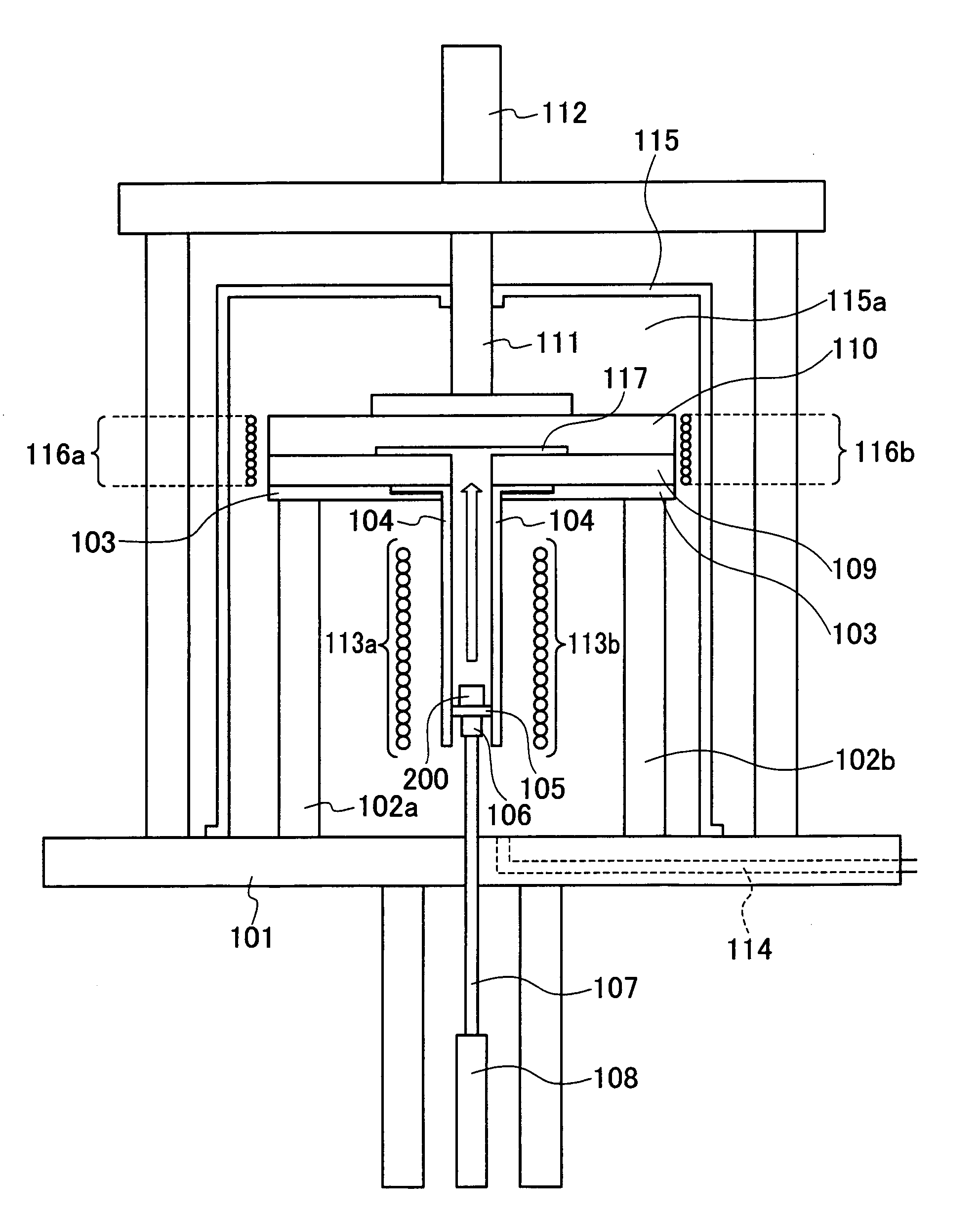
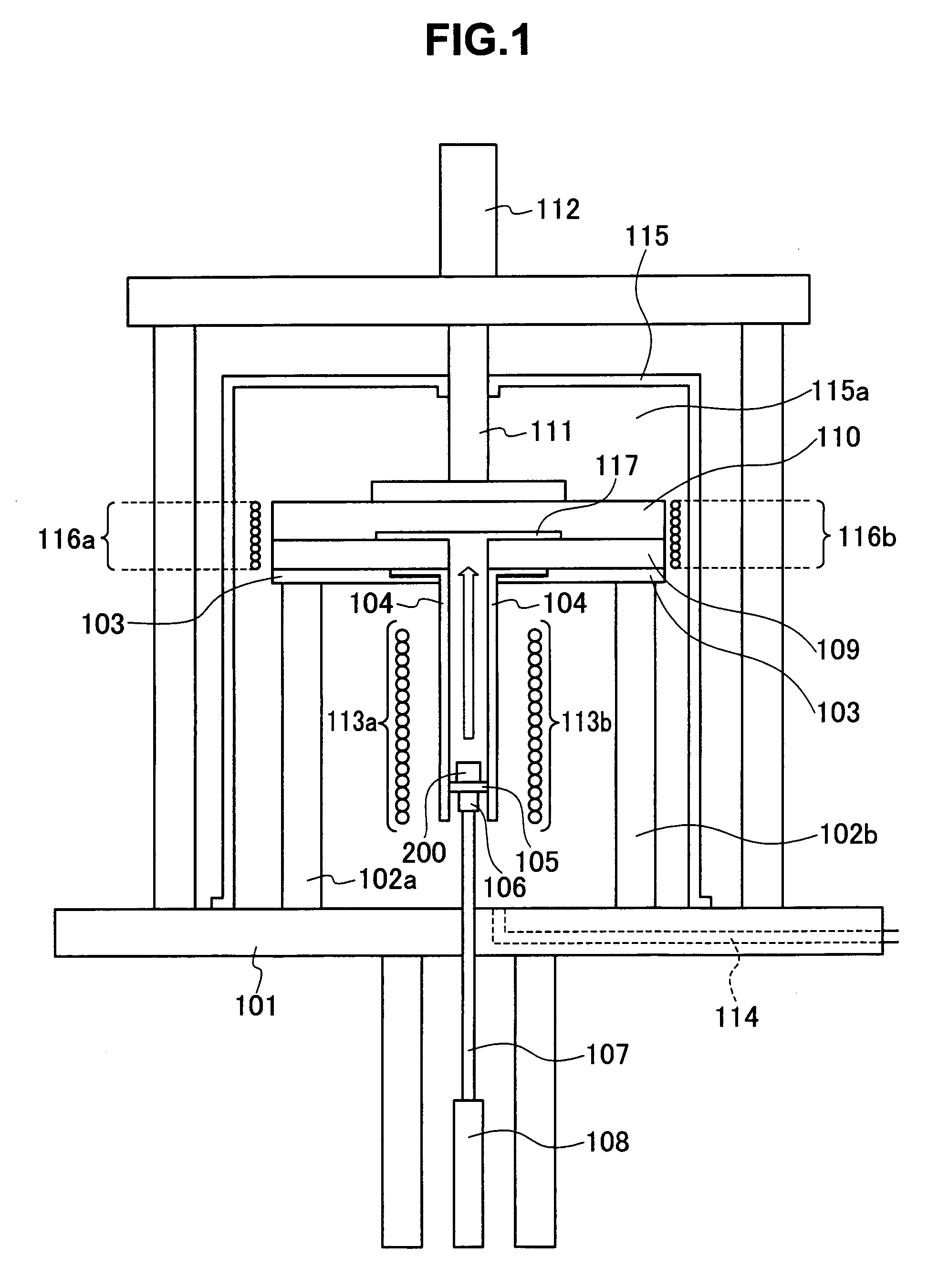
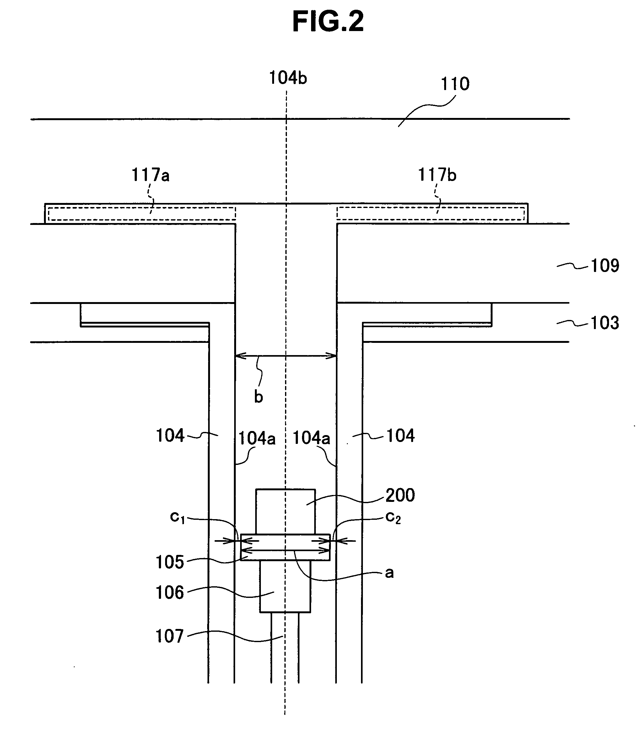
[0016] According to this diecast machine, the metal material heater melts the metal material by heating the metal material disposed on the plunger, the diecast machine possible to suppress a decrease in temperature of a melt, since the metal material (melt) does not poured from a melting furnace into the sleeve.
[0017] Moreover, since the mold is disposed above the upper side of the sleeve extending in the vertical direction and the plunger is moved upward in the vertical direction inside the sleeve, the diecast machine can make an area small where the metal material (melt) contacts the inside of the sleeve, it is possible to suppress temperature decrease of the melt.
[0018] In other words, the diecast machine can increase the ratio of the amorphous phase contained in the molded product. According to the aspect of the invention, the diecast method comprises the steps of: melting the metal material by heating the metal material disposed inside the sleeve; injecting a melt inside a cavity by pushing the melt upward in a vertical direction, the melt being the metal material melted in the melting step; and solidifying the melt inside the cavity by cooling the melt.

Problems solved by technology

Moreover, it is known that the large shaped metal glass (bulky metallic glass) can be manufactured by use of these methods (“Monthly Functional Material” CMC Publication, June / 2002, Vol. 22, No. 6, pp.
The squeeze diecasting method can mold the thin-walled molded product with fine surface properties, but can only mold a simple molded product taking a shape to allow pressure to be applied on the entire melt.
Moreover, since high-pressure is applied in the squeeze diecasting method, a metal mold tends to be damaged.
However, according to the prior art mentioned above (the horizontal diecasting method, the vertical diecasting method and the vacuum diecasting method), there has been the case that when the melt (metal material) is poured from a melting furnace into the sleeve, temperature of the melt is decreased and a heterogeneous nucleation is generated.
In other words, according to the prior art mentioned above, it has been difficult to increase a ratio of the amorphous phase contained in the molded product due to incorporating crystals into the molded product.

Method used


Image

  • Diecast machine and diecast method
  • Diecast machine and diecast method
  • Diecast machine and diecast method

Examples


examples

[0087] Hereinafter, one example of the present invention will be explained with reference to drawings. Firstly, criteria (evaluation criteria) to evaluate an amorphous degree according to the embodiment of the present invention will be explained with reference to the drawing. FIG. 5 is a diagram exhibiting criteria to evaluate the amorphous degree according to the one embodiment of the present invention.

[0088] As shown in FIG. 5, measurement results (XRD-Profile) by XRD method (X-Ray Diffractometer) and toughness of the molded product were adopted as evaluation criteria. Specifically, the molded product which had no sharp peak appearing in the XRD-profile and had the toughness greater than 130 KJ / m2 was evaluated at “G5”. On the other hand, the molded product which had sharp peak in the XRD-profile and had the toughness less than 70 KJ / m2 was evaluated at “G0”.

[0089] Next, one example of the XRD-profile will be explained with reference to the drawings. FIG. 6A is a graph depicting...


PUM

PropertyMeasurementUnit
Pressureaaaaaaaaaa
Pressureaaaaaaaaaa
Speedaaaaaaaaaa

Abstract

A diecast machine comprises: a sleeve extending in a vertical direction; a plunger moving upward in the vertical direction inside the sleeve; a mold disposed above an upper side of the sleeve; and a metal material heater configured to heat a metal material disposed on the plunger and melting the metal material.

Description

CROSS REFERENCE TO RELATED APPLICATIONS [0001] This application is based upon and claims the benefit of priority from prior Japanese Patent Application No. 2005-170055, filed on Jun. 9, 2005; the entire contents of which are incorporated herein by reference. BACKGROUND OF THE INVENTION [0002] 1. Field of the Invention [0003] This invention relates to a diecast machine to mold a molded product having an amorphous phase and to a diecast method. [0004] 2. Description of the Related Art [0005] It has been previously known that even in the case that a specific group of alloys is subjected to cooling at the cooling rate equal to or less than 100° C. / s, the specific group of alloys make glass transition to become an amorphous metal material (metallic glass) (for example, “Monthly Functional Material” CMC Publication, June / 2002, Vol. 22, No. 6, pp. 5-9). The metal glass possesses amorphous properties such as high strength, low Young's modulus and high elastic limit, and it is expected that ...

Claims


Application Information

Patent Timeline
IPC IPC(8): B22D17/12B22D27/04
CPCB22D17/12B22D17/14B22D17/2038B22D27/02B22D17/2209B22D17/30B22D21/022B22D17/2069
Inventor MURAMATSU, NAOKUNIINOUEKIMURA, HISAMICHI
Owner NGK INSULATORS LTD
Learn More