Eureka AIR delivers breakthrough ideas for toughest innovation challenges, trusted by R&D personnel around the world.

Dispensing spout

Inactive Publication Date: 2007-09-20
BONNER MARK
View PDF0 Cites 4 Cited by
  • Summary
  • Abstract
  • Description
  • Claims
  • Application Information

AI Technical Summary

Benefits of technology

[0013] According to an aspect of the present invention, there is provided a dispensing spout mountable to a liquid feeding means for delivering liquid from a liquid source, wherein the dispensing spout comprises: a casing formed with a dispensing passageway leading to a dispensing opening for delivery of the liquid; a venturi means within the casing to reduce the pressure within the dispensing passageway as liquid flows through it during use; and a control means. The control means has a closure member for blocking and unblocking the dispensing opening; and, as well, a deactivation means. The deactivation means includes an air conduit with an air opening wherein the air conduit is in communication with the dispensing passageway to permit the drawing of air into the dispensing passageway through the air opening when pressure is reduced by the venturi means. As well, however, it inhibits the flow of air into the dispensing passageway when the liquid level of dispensed liquid reaches the air opening and blocks access of air into the air opening. Upon that occurring, the deactivation means blocks the dispensing opening and prevents delivery of the liquid during use.

Problems solved by technology

As well, however, it inhibits the flow of air into the dispensing passageway when the liquid level of dispensed liquid reaches the air opening and blocks access of air into the air opening.

Method used


Image

  • Dispensing spout
  • Dispensing spout
  • Dispensing spout

Examples


Embodiment Construction

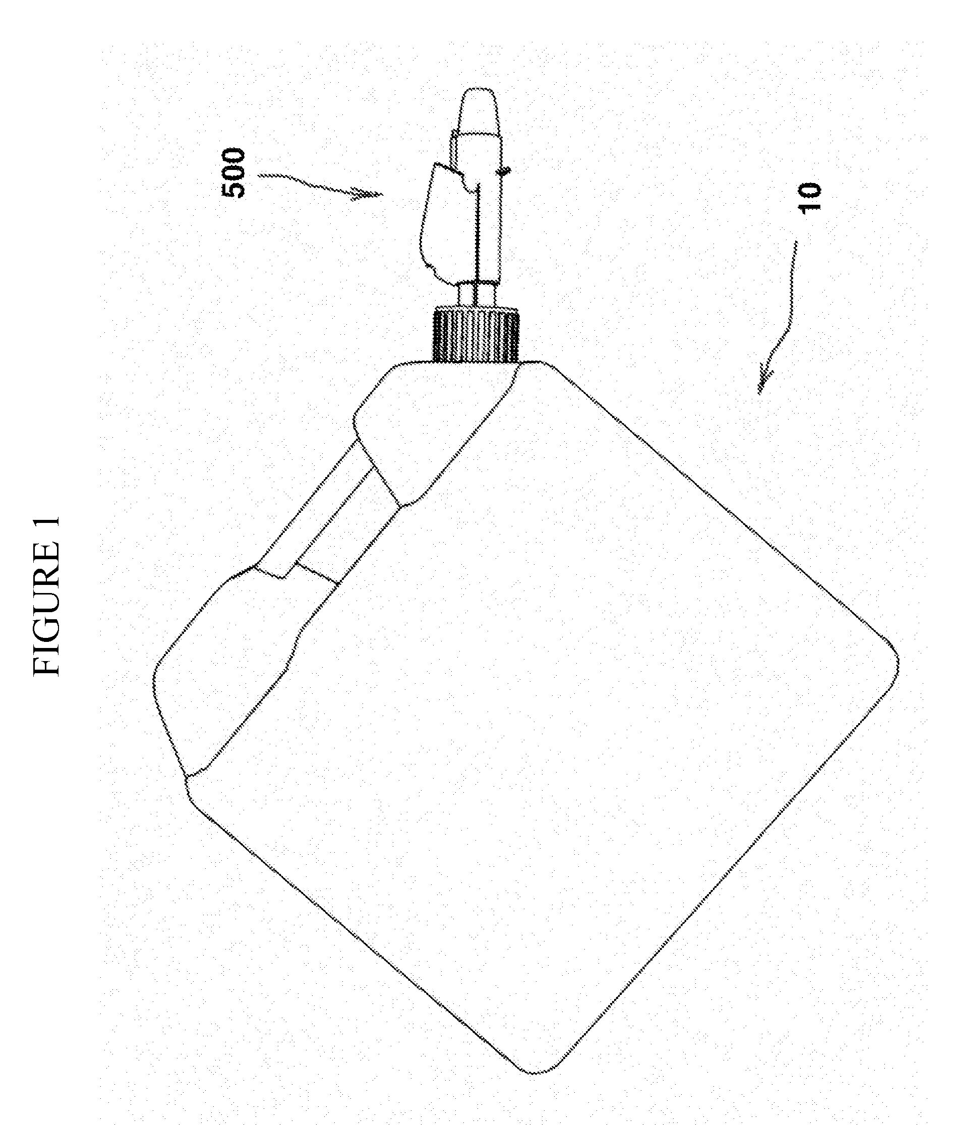
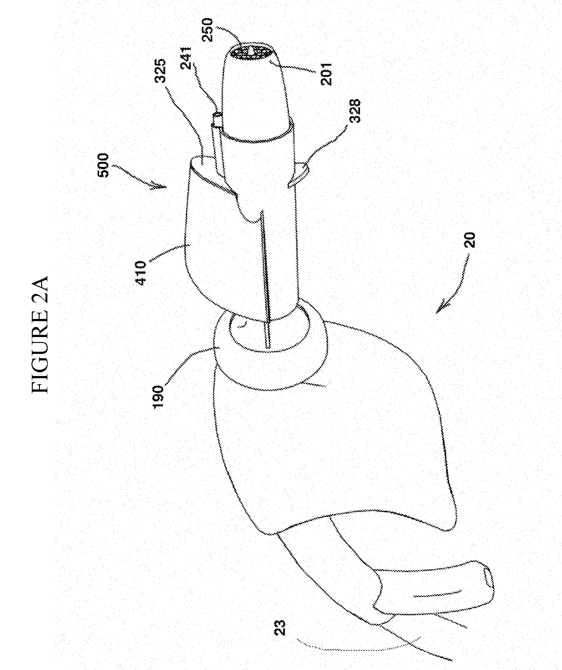
[0058] Referring to FIGS. 1 through 26 of the drawings, it will be noted that FIGS. 1 through 24 illustrate a first preferred embodiment of the dispensing spout of the present invention, and FIGS. 25 and 26 illustrate a second preferred embodiment of the dispensing spout of the present invention.

[0059] Reference will now be made to the FIGS. 1 through 24, which show a preferred embodiment of the dispensing spout of the present invention, as indicated by general reference numeral 20.

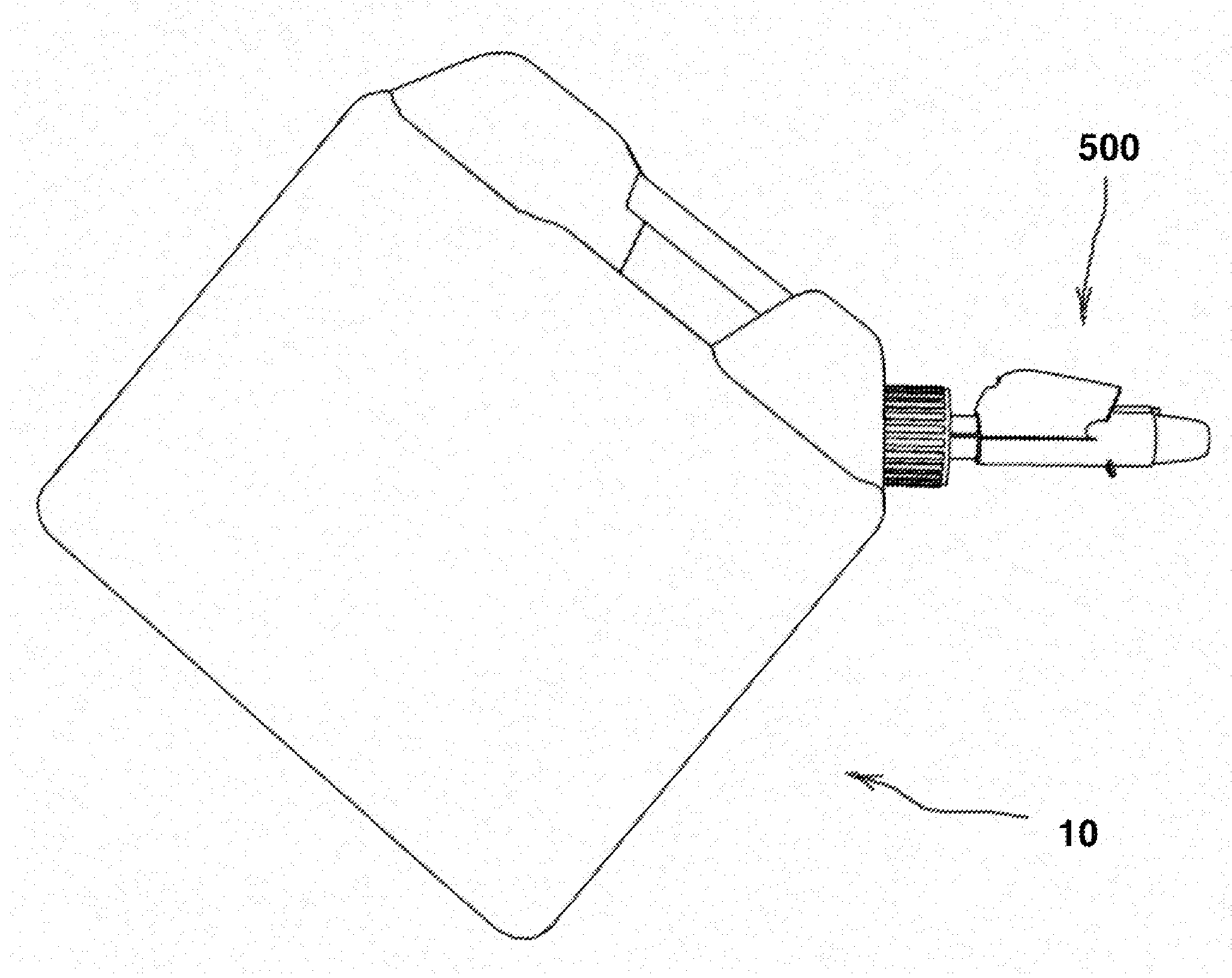
[0060] In this first aspect of the present invention, there is a dispensing spout 500 mountable to a liquid feeding means, such as a dispensing nozzle, hose, container, or the like, to provide a delivery system for delivering liquid from a liquid source, such as a portable fuel container 10, or the like, through a hose, such as a fuel hose, garden hose, or the like. The dispensing spout 500 comprises a casing 120 having an inlet 139 to receive liquid from the liquid source, such as the portable fuel con...


PUM

PropertyMeasurementUnit
Pressureaaaaaaaaaa
Levelaaaaaaaaaa
Resilienceaaaaaaaaaa

Abstract

This invention relates to a spout for a hose, nozzle or a container and to a hose, nozzle and a container used to dispense liquids into a receptacle from a liquid source such as a gas container, delivery hose or pump. In each case, there is a spout means having a delivery trunk body formed with a dispensing passageway leading to a dispensing opening for delivery of the liquid; a venturi means within the delivery trunk to reduce the pressure within the dispensing passageway as liquid flows through it during use; a control means; said control means having a deactivation means, said deactivation means including an air conduit with an air opening, the air conduit being in communication with the dispensing passageway to permit the drawing of air into the dispensing passageway through the air opening when pressure is reduced by the venturi means, but inhibiting the flow of air into the dispensing passageway when the air opening is blocked or covered as the liquid level of dispensed liquid reaches the air opening and cuts off access of air into the air opening; a deactivation means to shut off the dispensing opening when the air opening is closed to inhibit air from entering during use.

Description

[0001] This application claims the benefit of the filed U.S. Provisional Patent Application numbered 60 / 748,047, entitled V-Spout Auto-Closure & Auto Shutoff Venturi Spout, which is here by incorporated by reference.FIELD OF THE INVENTION [0002] The present invention relates to a spout for a hose, nozzle or a container and to a hose, nozzle and a container used to dispense liquids into a receptacle from a liquid source such as a gas container, delivery hose or pump. BACKGROUND OF THE INVENTION [0003] It is a problem with the present art of liquid delivery, where delivery is accomplished by a nozzle and hose configuration or from a portable container, such as is the case with gasoline, that there can be unwanted dripping and spillage. For instance, the nozzle can often still be operable after the receptacle has filled. As well, in the case of containers, with no automatic shut-off, the fuel keeps on pouring even after the receptacle is filled. [0004] Devices which permit delivery of ...

Claims


Application Information

Patent Timeline
IPC IPC(8): B65B57/06B67D7/04B67D7/36B67D7/48B67D7/46
CPCB67D7/42B67D7/005
Inventor BONNER, MARK
Owner BONNER MARK
Why Eureka
Eureka Blog
Learn More