
Decorative button

a technology of decorative buttons and buttons, applied in the field of decorative buttons, can solve the problems of reducing the total weight of the product and the button becomes relatively heavy, and achieve the effect of enhancing the cap-supporting capacity of the cap-supporting portion

Inactive Publication Date: 2007-09-20
YKK CORP
View PDF10 Cites 2 Cited by
  • Summary
  • Abstract
  • Description
  • Claims
  • Application Information

AI Technical Summary

Benefits of technology

[0008]A decorative button according to an aspect of the invention is fixed to a fabric. The decorative button includes: a base member; and a cap member undetachably disposed on the base member, the cap member forming an outer surface of the decorative button. The base member abuts to a middle portion of a rear surface of the cap member to support the cap member. The base member includes a supporting portion which prevents a deformation of the cap member.
[0009]In the decorative button according to the aspect of the invention, the supporting portion of the base member supports, from the rear side of the cap member, the middle portion of the cap member projecting in a dome-like shape. Accordingly, in attaching of the button to the fabric or when the button is in use, the risk of deforming the dome shape of the cap can be reduced even when a load or an impact is applied on the cap.
[0012]In a decorative button according the invention, a top portion of the supporting portion of the base member curves along the rear surface of the cap member to make a plane-contact to the cap member. Specifically, the top portion of the supporting portion of the base member is adapted to make not a point-contact but a plane-contact to the rear surface of the cap member. The contacting surface of the supporting portion is not horizontal but curved along the rear surface of the curving cap. Accordingly, the cap-supporting capacity of the cap-supporting portion can be enhanced.

Problems solved by technology

When the dome-shaped decorative button is a solid die cast product, the button becomes relatively heavy.
Accordingly, especially when many buttons are used, reduction in total weight of the product may be hindered.

Method used


Image

  • Decorative button
  • Decorative button
  • Decorative button

Examples


Embodiment Construction

)

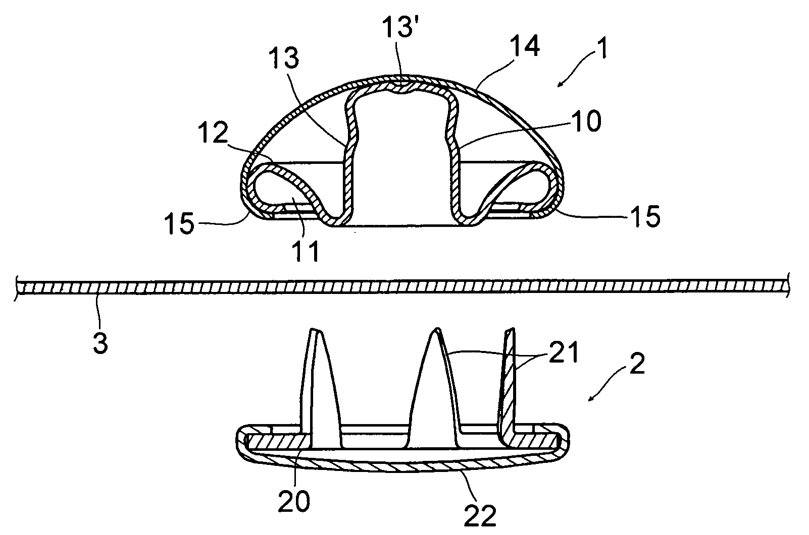
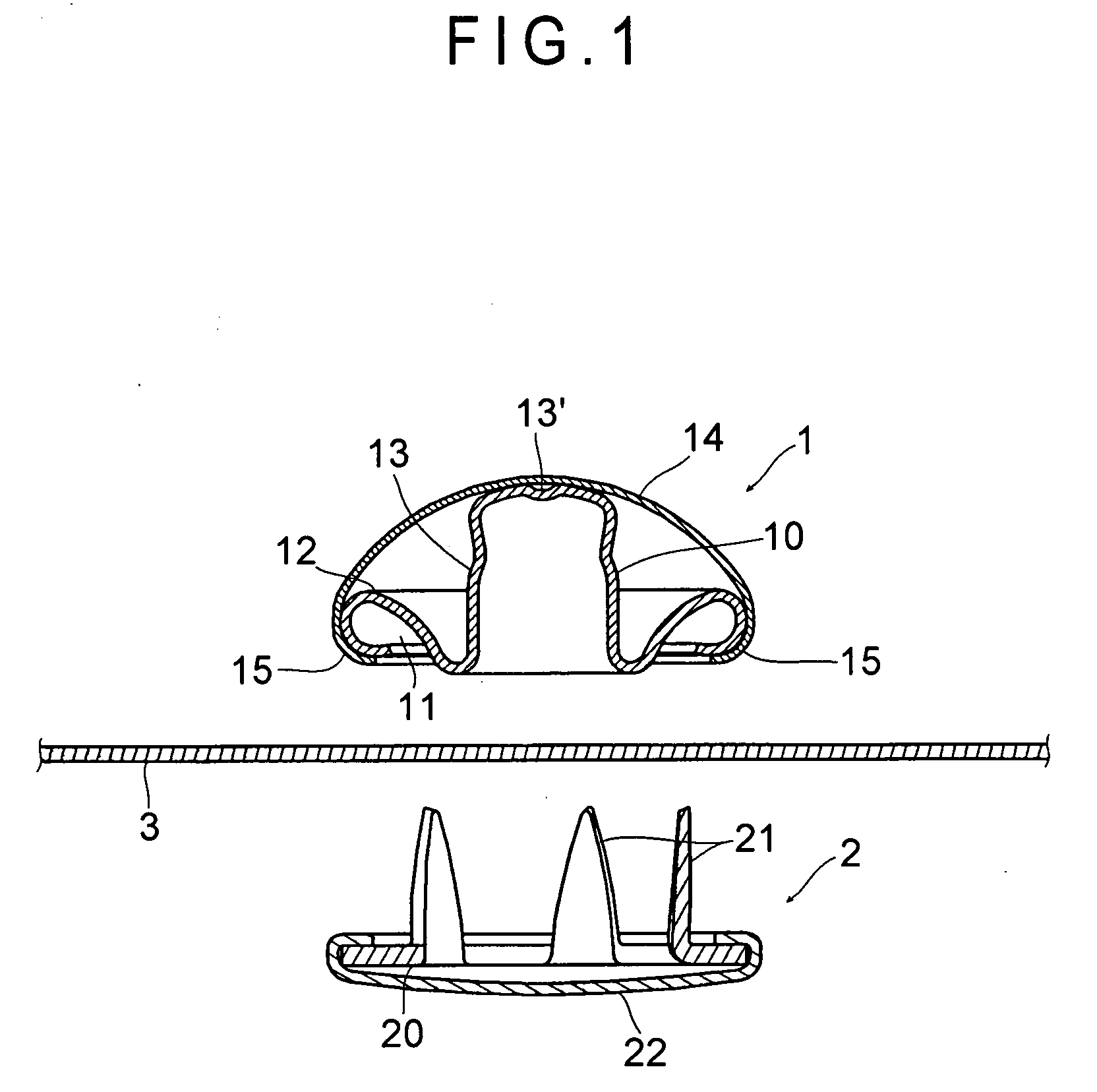
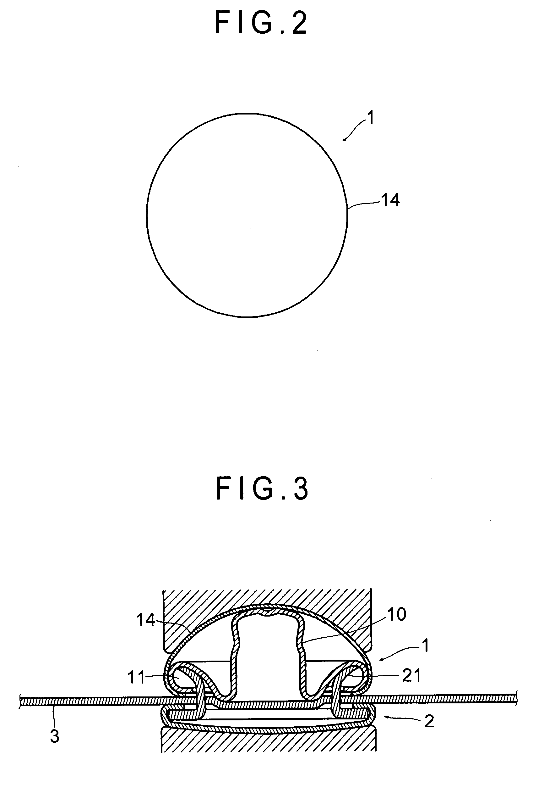
[0018]A preferred embodiment of a decorative button according to the present invention will be described below with reference to the attached drawings. FIG. 1 is a cross section showing a decorative button 1 and a fixing member (a cap prong) 2 vertically facing to each other with a fabric 3 therebetween, the decorative button 1 and the fixing member 2 to be fixed to the fabric 3. FIG. 2 is a plan view of the decorative button 1. FIG. 3 is a cross section showing the decorative button 1 attached to the fabric 3.

[0019]The decorative button 1 includes a base member 10 and a dome-shaped cap member 14 disposed on the base member 10, both members being made of brass, stainless steel, aluminum or the like and formed by drawing. The cap member 14 forms an outer surface (a convex and spherical surface) of the doom shape of the decorative button 1. The base member 10 includes a ring-shaped flange portion 12 and a cap-supporting portion 13. The flange portion 12 includes a prong-accommodating...


PUM


Abstract

A decorative button (1) includes a base member (10) and a cap member (14). The base member (10) includes a prong-accommodating portion (11) that receives a prong portion (21) of a fixing member (2). The cap member (14) is disposed on the base member (10) and forms an outer surface of the decorative button (1). The base member (10) is provided with a cap-supporting portion (13) which abuts to a middle portion of a rear surface of the cap member (14) to support the cap member (14), thereby preventing a deformation of the cap member (14). A top portion (13′) of the cap-supporting portion (13) is a plane to abut to the rear surface of the cap member (14) along the curving of the rear surface.

Description

BACKGROUND OF THE INVENTION[0001]1. Field of the Invention[0002]The present invention relates to a decorative button. Specifically, the invention relates to a dome-shaped decorative button.[0003]2. Description of Related Art[0004]Dome-shaped decorative buttons are widely used for decoration of garments, shoes and bags, especially for decoration of leather and denim products due to an appearance of a head thereof like an embedded pin or rivet of a dome-like arched shape when the button is fixed to a fabric.[0005]One example of the dome-shaped buttons is disclosed in JP-U-48-97104. However, in a process for fixing the button to the fabric or in use, the dome made of a metal plate of the button might be deformed relatively easily when a load is applied on a surface of the dome.[0006]When the dome-shaped decorative button is a solid die cast product, the button becomes relatively heavy. Accordingly, especially when many buttons are used, reduction in total weight of the product may be h...

Claims


Application Information

Patent Timeline
IPC IPC(8): A44B1/42
CPCA44B1/42Y10T24/3611A44B1/44
Inventor KUBOTA, NARIKOOMORI, KOJI
Owner YKK CORP
Learn More