
Apparatus and method for menu item selection

Inactive Publication Date: 2007-09-13
SPX CORP
View PDF7 Cites 5 Cited by
  • Summary
  • Abstract
  • Description
  • Claims
  • Application Information

AI Technical Summary

Benefits of technology

[0008]The foregoing needs are met, to a great extent, by the present invention, wherein in one aspect an apparatus is provided that in some embodiments provides a user interface resembling a mechanical switch configured to facilitate the se

Problems solved by technology

Battery chargers and tester / chargers are increasingly incorporating electronic components, with their functions determined and controlled by computer software, such that mechanical switches become less suitable for selecting functions.
Such user interfaces for software-driven devices and systems have a shortcoming, however, in that keypads and continuously rotatable knobs or wheels do not provide the tactile and visual feedback of mechanical switches.
Since these devices are generally short and squat, the user often needs to bend or stoop over in order to access the controls.
Alternatively, the entire unit may be mounted such that the controls are more easily accessible, though this has the undesirable effect of rendering the unit substantially immobile as well as potentially unsightly.
However, since extant battery charging systems are generally powered via a fixed AC power outlet, use of the BOOST function may be limited to environments where such power is readily available.
This, of course, may not be the case for all disabled vehicles.
In these cases, a separate battery booster pack must be used to start the vehicle before the vehicle can be moved to the battery testing or testing / charging equipment, thus increasing the time necessary to diagnose the battery.
Though an internal, rechargeable battery could be integrated into the battery charger or tester / charger to partially address this shortcoming, this increases the cost of the component.

Method used


Image

  • Apparatus and method for menu item selection
  • Apparatus and method for menu item selection
  • Apparatus and method for menu item selection

Examples


Embodiment Construction

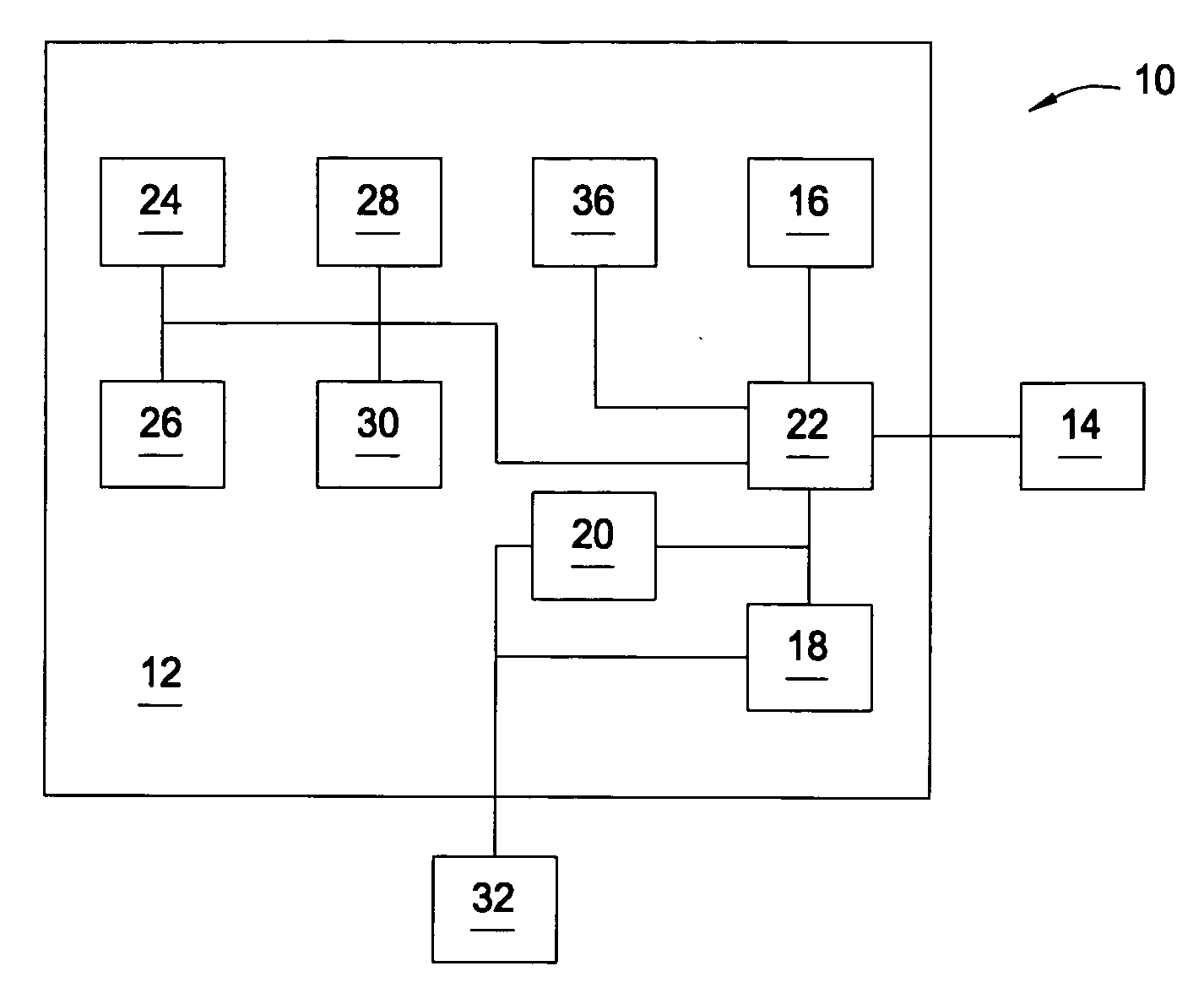
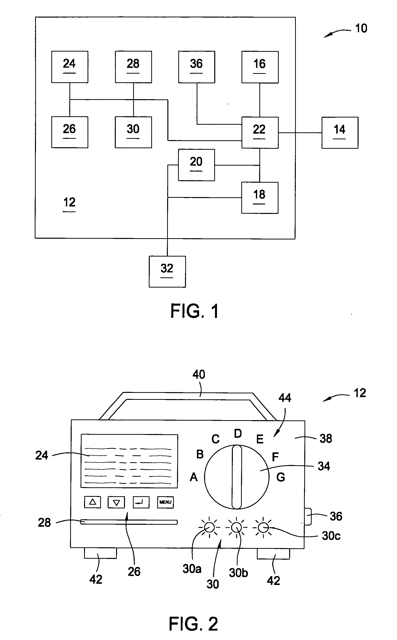
[0020]The invention will now be described with reference to the drawing figures, in which like reference numerals refer to like parts throughout. A user interface for a software-driven system includes a switch selectable between a plurality of discrete positions, a database of functions performable by an execution unit within the system, and software configured to correlate positions of the switch with functions within the database. By placing the switch in a particular discrete position, the user can select a function from the database. The indicia may be interchangeable, and the database and software upgradeable, such that additional or different functions may be selected via the user interface without resort to substantial hardware upgrades. This permits a user to provide input to a software-driven system through an interface that preserves the visual and tactile feedback of familiar mechanical systems.

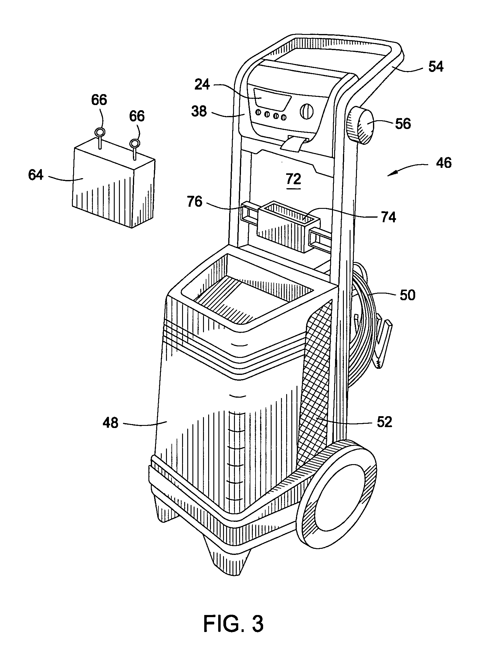
[0021]A block diagram of an exemplary software-driven system 10, such as a bat...


PUM


Abstract

A user interface for a software-driven system includes a switch selectable between a plurality of discrete positions, a database of functions performable by an execution unit within the system, and software configured to correlate positions of the switch with functions within the database. Indicia may be provided at the various discrete positions identifying the functions corresponding to these positions. By placing the switch in a particular discrete position, the user can select a function from the database. The indicia may be interchangeable, and the database and software upgradeable, such that additional or different functions may be selected via the user interface without resort to substantial hardware upgrades. A display and optical indicators may provide system state information to the user. A software-driven battery charging / testing system includes means for executing battery-related functions, means for storing a database of battery-related functions, and means for selecting from the database.

Description

CROSS-REFERENCE TO RELATED APPLICATIONS[0001]This application claims priority to provisional U.S. patent application entitled, Apparatus and Method for Remote Battery Tester / Charger Control, filed Mar. 10, 2006, having a Ser. No. of 60 / 780,837, the disclosure of which is hereby incorporated by reference in its entirety.FIELD OF THE INVENTION[0002]The present invention relates generally to battery chargers and testers / chargers. More particularly, the present invention relates to an apparatus and method for allowing a user to select from a menu of options in a software-driven battery charger or tester / charger.BACKGROUND OF THE INVENTION[0003]Users of battery chargers and tester / chargers are often required to select from a variety of functions that the charger or tester / charger is capable of performing. Many extant devices feature a rotary knob, connected to a mechanical switch that the user turns to select a desired function, with each position of the knob corresponding to a particula...

Claims


Application Information

Patent Timeline
IPC IPC(8): G01N27/416
CPCH01M10/48H01M10/44Y02E60/10
Inventor KRAMPITZ, SCOTTRAICHLE, KURT
Owner SPX CORP
Learn More