Reduction gear for geared motor, geared motor, and product group thereof

Inactive Publication Date: 2008-05-13
SUMITOMO HEAVY IND LTD
View PDF21 Cites 8 Cited by
  • Summary
  • Abstract
  • Description
  • Claims
  • Application Information

AI Technical Summary

Benefits of technology

[0010]The present invention was developed to solve these problems. It is therefore an object of the present invention to facilitate the selective combination of a reduction gear and a motor, which can be used flexibly and reasonably according to its application.
[0012]That is, the intermediate orthogonal gear head having the orthogonal transfer mechanism can be coupled to the rear stage parallel gear head having the parallel shaft reduction mechanism, thereby making it possible to change the rotational direction of power delivered from the motor into an orthogonal direction and reduce the rotational speed. In this arrangement, since each gear head is formed in a separate casing, it is possible to use the intermediate orthogonal gear head itself as a reduction gear for performing orthogonal transfer or the rear stage parallel gear head itself as a reduction gear for performing parallel shaft speed reduction, respectively.
[0014]It is also possible to provide a geared motor having the aforementioned effects by integrally coupling these reduction gears and motors to each other.
[0015]Such geared motors would offer a much greater advantage when provided in a product group which has multiple types of at least one of the motor, the intermediate orthogonal gear head, and the rear stage parallel gear head and allows one of the multiple types to be selectively replaceable.
[0016]The geared motor provided in a product group allows the user to replace either the motor, the intermediate orthogonal gear head, or the rear stage parallel gear head as required with the other components remaining unchanged, thereby making it possible to reduce delivery lead times and product stocks as well as development cost and the price of the reduction gear.

Problems solved by technology

This has raised a stock cost of the reduction gear for reduction gear manufactures, and has raised a purchase price of the reduction gear for reduction gear users.
Furthermore, for gear arrangement convenience in the reduction gear, input and output shafts were restrictively positioned, resulting in a restricted position (or direction) for attachment of the reduction gear.
Thus, the reduction gear could not be said to meet user needs (or user usability).

Method used


Image

  • Reduction gear for geared motor, geared motor, and product group thereof
  • Reduction gear for geared motor, geared motor, and product group thereof
  • Reduction gear for geared motor, geared motor, and product group thereof

Examples


Embodiment Construction

[0035]Now, the present invention will be explained below in more detail with reference to the accompanying drawings in accordance with embodiments.

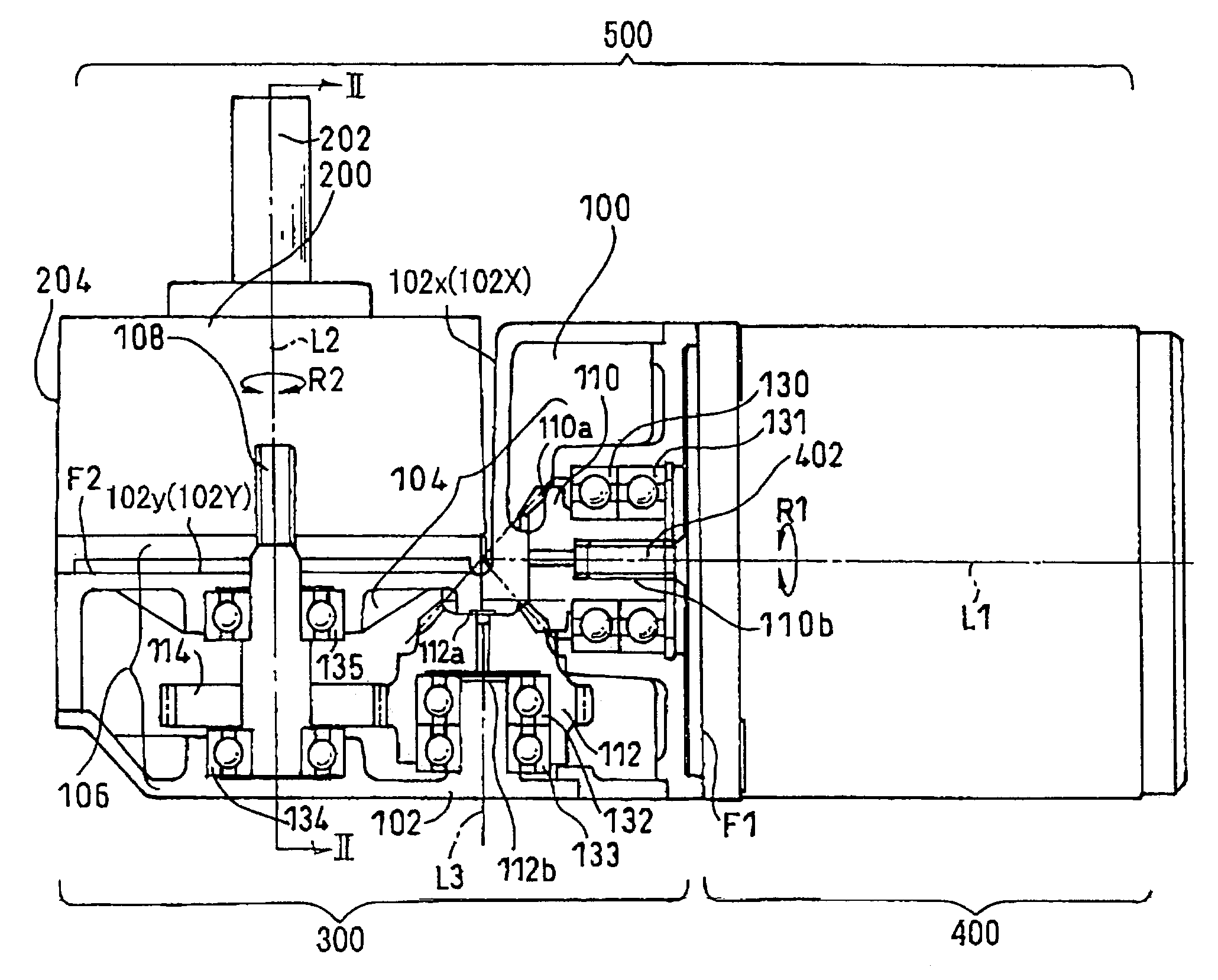
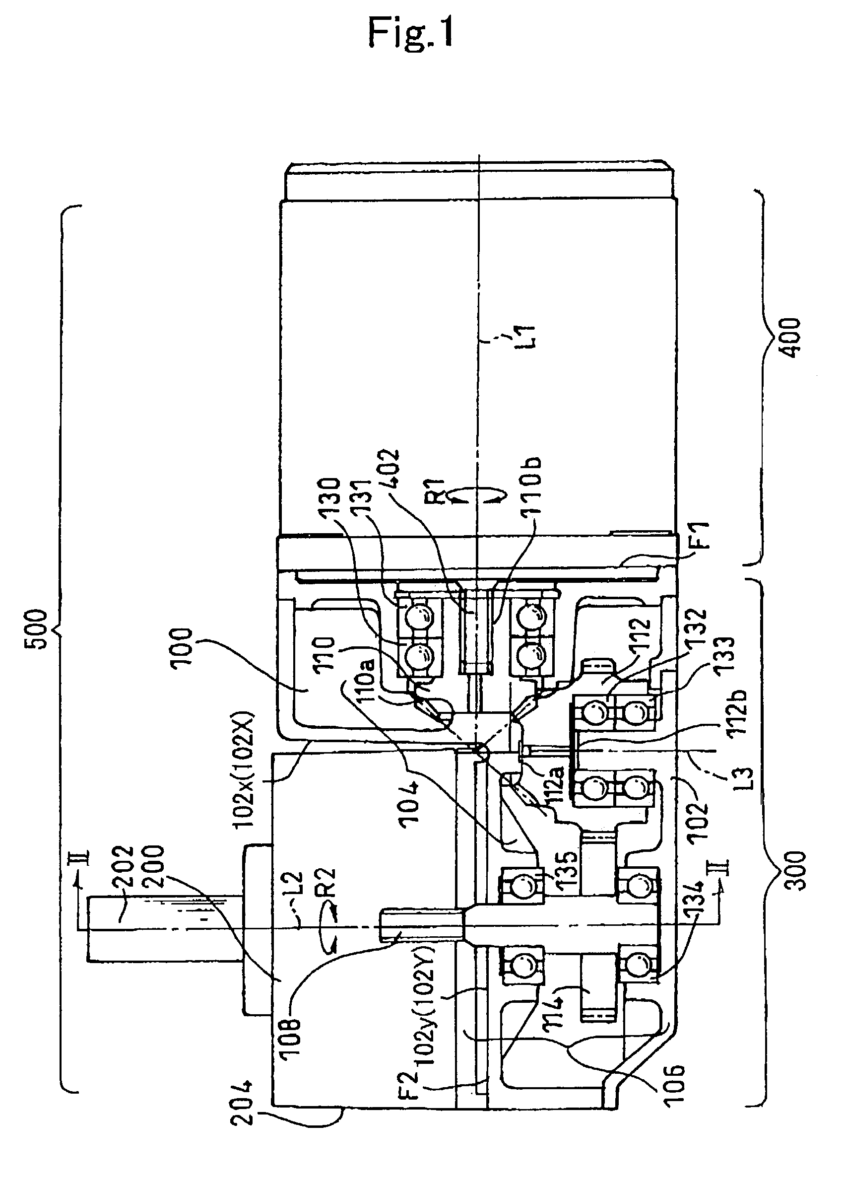
[0036]FIG. 1 is a cross-sectional view showing a geared motor 500 incorporating a reduction gear for use therewith according to the present invention. The geared motor 500 includes a motor 400 and a reduction gear 300, which includes an intermediate orthogonal gear head 100 and a rear stage parallel gear head 200.

[0037]On an attachment face F1 between the motor 400 and the intermediate orthogonal gear head 100, the intermediate orthogonal gear head 100 can be attached to the motor 400 at any one of the positions separated at angular intervals of 90 degrees about an output shaft (hereinafter simply referred to as the “motor shaft”) 402 of the motor 400 along the circumferential direction R1 of the motor shaft 402. The motor 400 and the intermediate orthogonal gear head 100 are coupled to each other with bolts (not shown).

[0038]Furthermore,...


PUM


Abstract

A reduction gear for forming a geared motor having a motor and a reduction gear is provided. The reduction gear for a geared motor includes an intermediate orthogonal gear head having an orthogonal transfer mechanism for changing a rotational direction of power delivered from the motor into an orthogonal direction and houses the orthogonal transfer mechanism in a separate intermediate casing. The reduction gear further includes a rear stage parallel gear head having a parallel shaft reduction mechanism including an output shaft serving as a final output shaft of the geared motor when the geared motor is formed, the rear stage parallel gear head being capable of directly connecting to a rear stage of the intermediate orthogonal gear head, with the parallel shaft reduction mechanism being housed in a separate rear stage casing.

Description

BACKGROUND OF THE INVENTION[0001]1. Field of the Invention[0002]The present invention relates to a reduction gear, a geared motor, and a product group thereof for use with industrial and transportation machinery and so forth.[0003]2. Description of the Related Art[0004]Conventionally it is known a reduction gear of an orthogonal or parallel shaft type for reducing power delivered from a motor or the like or for changing its rotational direction. In general, a motor is combined with the orthogonal shaft type reduction gear to change the rotational direction of power delivered from the motor, or with the parallel shaft type reduction gear to reduce only the speed thereof.[0005]Alternatively, when the rotational direction needs to be changed and the speed needs to be reduced at the same time, a geared motor may be constructed in a combination of a motor and a reduction gear in which both the orthogonal transfer mechanism and the parallel shaft reduction mechanism are housed in one casi...

Claims


Application Information

Patent Timeline
IPC IPC(8): F16H3/44F16H1/14F16H1/20F16H57/033H02K7/116
CPCF16H57/033H02K7/1166F16H1/14F16H1/20Y10T74/1966Y10T74/19684Y10T74/2186Y10T74/19647F16H2057/0335F16H1/12
Inventor HAGA, TAKASHITAMURA, MITSUHIRO
Owner SUMITOMO HEAVY IND LTD
Why Eureka
Try Eureka