
Ankle stabilizing apparatus having a pivotable stiffening unit

a technology of stabilizing apparatus and pivoting unit, which is applied in the field of flexible body member and pivoting unit, can solve the problems of limiting the movement of the ankle, affecting the healing effect of the ankle, so as to achieve the effect of minimizing the occurrence of ankle sprains

Inactive Publication Date: 2007-09-13
MEDICAL SPECIALTIES
View PDF17 Cites 22 Cited by
  • Summary
  • Abstract
  • Description
  • Claims
  • Application Information

AI Technical Summary

Benefits of technology

[0010] It is therefore an object of the present invention to provide an ankle stabilizing apparatus which effectively minimizes the occurrence of ankle sprains without unduly restricting the desirable motions of the ankle during athletic activities.
[0011] It is also an object of the invention to provide an ankle stabilizing apparatus which effectively minimizes lateral movement of the upper portions of the ankle relative to the lower portions of the foot.
[0012] It is a further object of the present invention to provide an ankle stabilizing apparatus that provides sufficient support without unduly restricting forward and rearward movement of upper portions of ankle with respect to the foot.
[0013] It is still a further object of the invention to provide an ankle stabilizing apparatus that can be readily incorporated into existing body members in a secure fashion.
[0014] The invention meets these objectives with an ankle stabilizing apparatus capable of minimizing lateral movement of upper portions of the body member and ankle with respect to lower sections of the body member and foot, without obstructing forward and rearward movement of upper portions of the body member and ankle with respect to the lower sections of the body member and ankle. In particular, the invention is an ankle stabilizing apparatus having a flexible body member and a stiffening unit secured to selected portions of the body member, wherein the stiffening unit includes a base and a cuff that are pivotably connected.

Problems solved by technology

As known to participants in athletics, the ankle is often injured as a result of contact with other participants or items of equipment, or as a result of the ankle assuming an unnatural position during play.
Specifically, ankles are particularly vulnerable to sprains, fractures, and the like.
For example, taping may restrict all motion of the ankle, both desirable and undesirable, because the tape is wound circumferentially around the ankle.
The restrictive characteristics of taping thus hinder the athlete's ability to perform.
Further, tape tends to stretch and loosen as the athlete moves, thereby decreasing its effectiveness in supporting the ankle.
Nevertheless, undesirable movement of the ankle may occur as a result of lateral-as well as vertical-movement of upper portions of the body member relative to lower portions of the body member.
Further, known devices tend to prohibit the forward movement of upper portions of ankle with respect to the foot (i.e., dorsiflexion) and rearward movement of upper portions of ankle with respect to the foot (i.e., flexion).
Unfortunately, the brace fails to provide sufficient support for athletes participating in strenuous activities (e.g., basketball and football).
Specifically, the pivoting rear section permits lateral movement of the left and right legs, thus failing to prevent inversion and eversion of the ankle during strenuous exercise.
Furthermore, the '886 patent fails to provide sufficient support about portions of the upper ankle.
In other words, the cuff structure of the '886 patent does not extend sufficiently about portions of the upper ankle to provide the support necessary to minimize injury.
The structural configuration of the foot support shell prohibitively limits the natural movement of the foot during walking and running.
Further, the three straps disclosed necessarily secure the brace to the foot at fixed points and fail to provide support about the entire ankle.
Unfortunately, the known stiffening units described above are single unit pieces that are not capable of being readily incorporated into a flexible boot shaped body member in a secure fashion that will provide sufficient support for the individual.

Method used


Image

  • Ankle stabilizing apparatus having a pivotable stiffening unit
  • Ankle stabilizing apparatus having a pivotable stiffening unit
  • Ankle stabilizing apparatus having a pivotable stiffening unit

Examples


Embodiment Construction

[0024] The present invention will now be described more fully hereinafter with reference to the accompanying drawings, in which a preferred embodiment of the invention is shown. This invention may, however, be embodied in many different forms and should not be construed as limited to the embodiments set forth herein. Rather, these embodiments are provided so that this disclosure will be thorough and complete, and will fully convey the scope of the invention to those skilled in the art. Like numbers refer to like elements throughout.

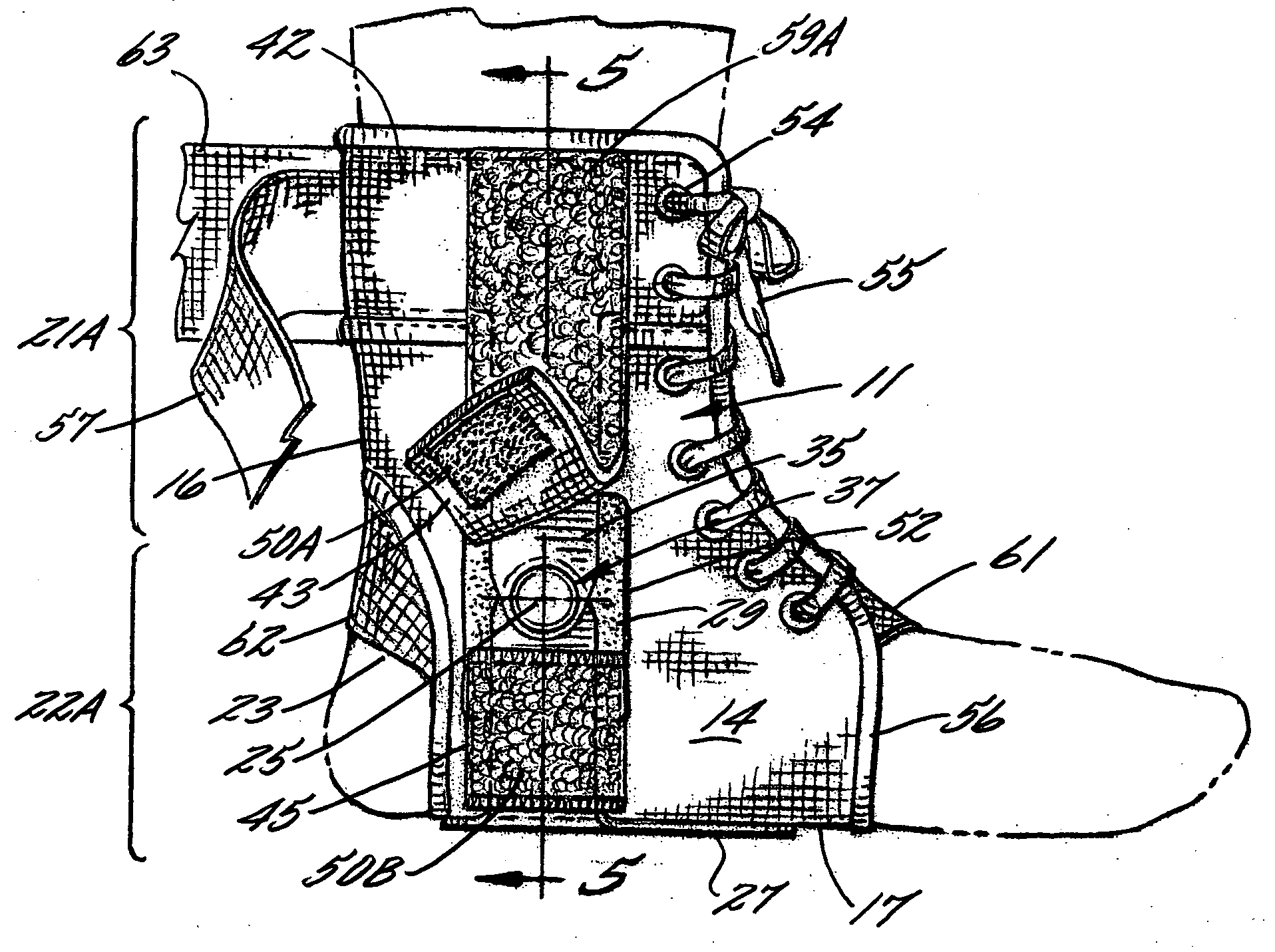
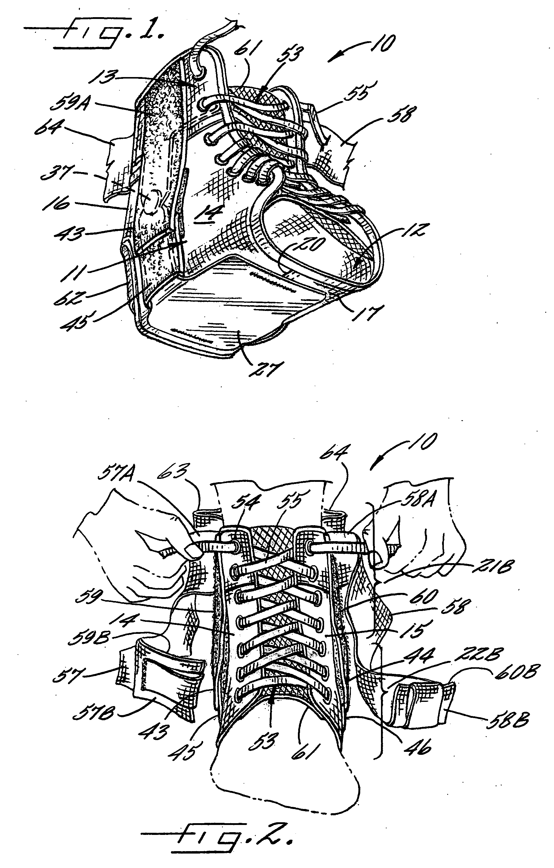
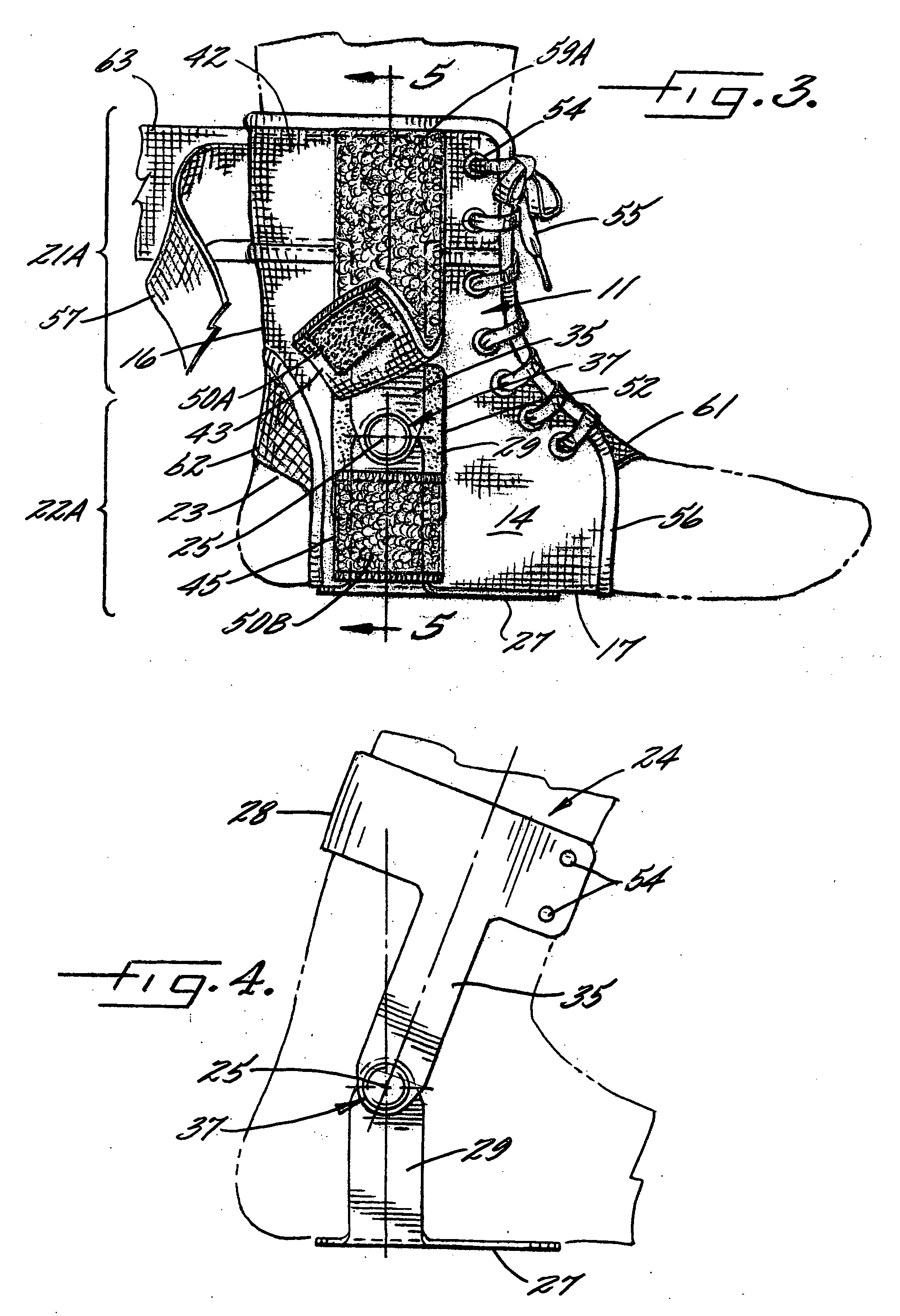
[0025] The ankle stabilizing apparatus of the present invention is generally indicated at 10. As illustrated, the apparatus 10 may be worn without an athletic sock such that interior surfaces of the apparatus contact skin of the wearer. Alternatively, the apparatus 10 may be worn over an athletic sock such that interior surfaces of the apparatus contact the sock (not shown). The apparatus 10 is configured for wear on the right or left foot. Therefore FIG...


PUM


Abstract

An apparatus for stabilizing movement of an ankle comprises in one embodiment a flexible body member for receiving a foot and a stiffening unit secured to selected portions of the body member such that the stiffening unit minimizes movement of upper portions of the body member with respect to lower portions of the body member, without obstructing forward and rearward movement of the upper portions of the body member with respect to the lower portions of the body member.

Description

FIELD OF THE INVENTION [0001] The invention relates to an ankle stabilizing apparatus for minimizing inversion and eversion of a foot, and more specifically, to a flexible body member and a pivotable stiffening unit secured to selected portions of the body member, wherein the stiffening unit minimizes movement of upper portions of the body member with respect to lower portions of the body member, without obstructing forward and rearward movement of the upper portions of the body member with respect to the lower portions of the body member. BACKGROUND OF THE INVENTION [0002] As known to participants in athletics, the ankle is often injured as a result of contact with other participants or items of equipment, or as a result of the ankle assuming an unnatural position during play. Injuries typically occur during motions typically associated with athletics such as running, jumping, falling, or the like. Specifically, ankles are particularly vulnerable to sprains, fractures, and the like...

Claims


Application Information

Patent Timeline
Patent Type & Authority Applications(United States)
IPC IPC(8): A61F5/00
CPCA61F5/0127
Inventor GAYLORD, ROBERT SCOTTGAYLORD, ERIC LEE
Owner MEDICAL SPECIALTIES
Learn More