
Combined Electro-Magnetic Acoustic Transducer

a combined electromagnetic and acoustic transducer technology, applied in the field of bond integrity evaluation, can solve the problems of increasing production costs, reducing the coupling between the piezoelectric device and the casing, and reducing the efficiency of the piezoelectric device,

Active Publication Date: 2007-09-13
BAKER HUGHES INC
View PDF41 Cites 65 Cited by
  • Summary
  • Abstract
  • Description
  • Claims
  • Application Information

AI Technical Summary

Problems solved by technology

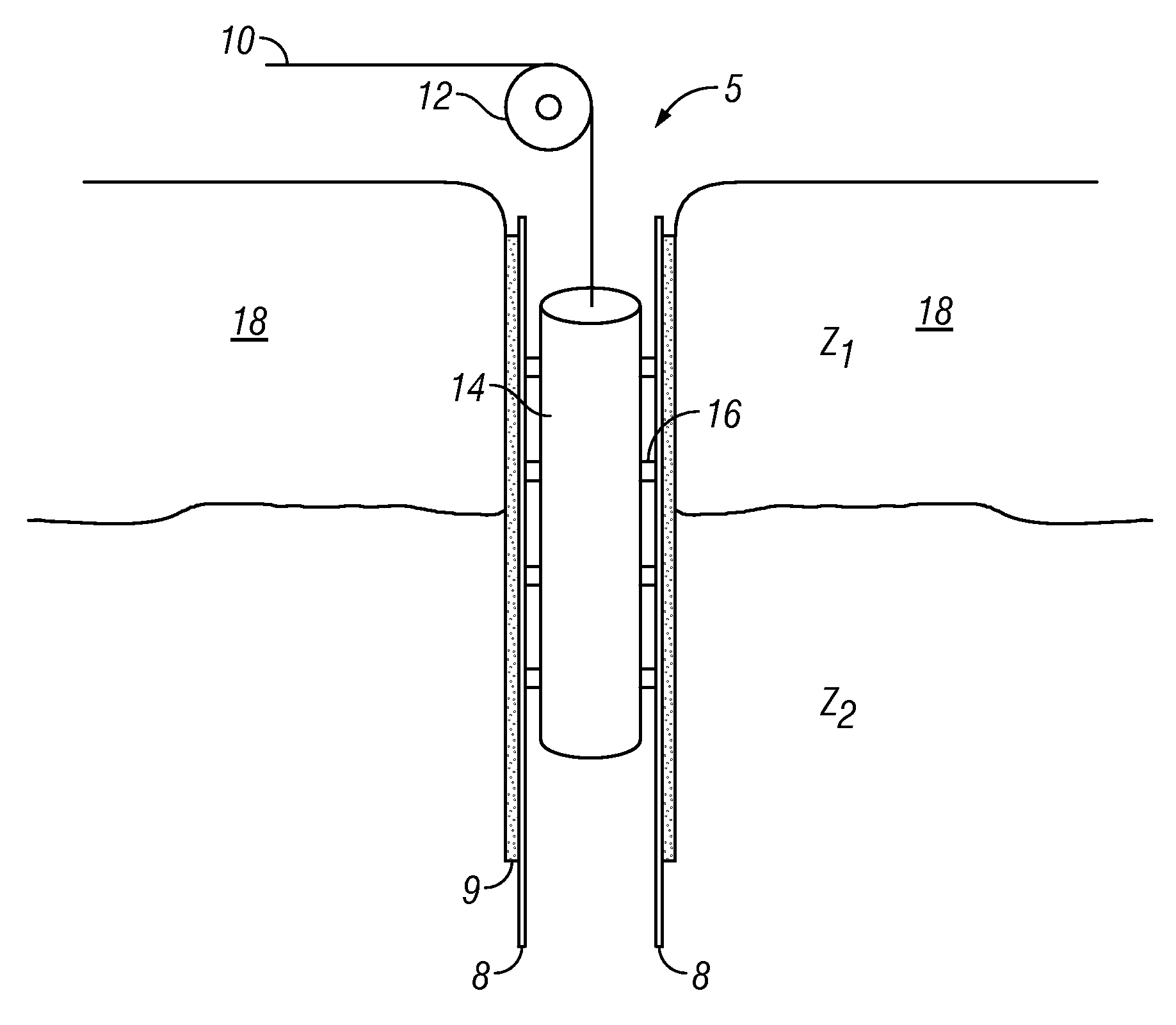
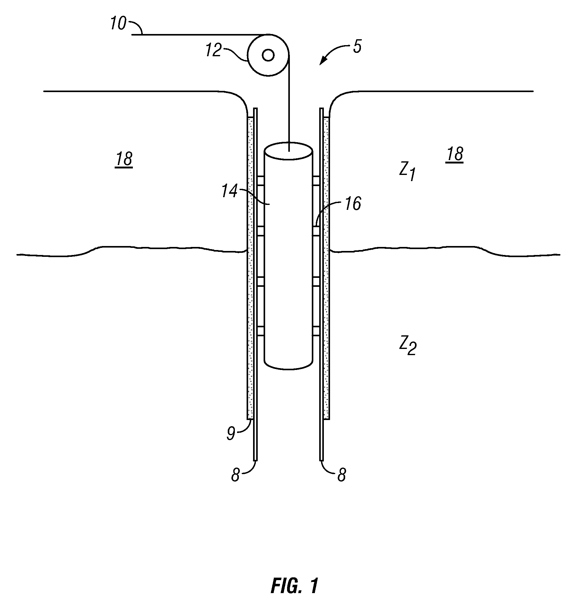
Should the cement 9 surrounding the casing 8 be defective and fail to provide isolation of the adjacent zones, water or other undesirable fluid can migrate into the hydrocarbon producing zone thus diluting or contaminating the hydrocarbons within the producing zone, and increasing production costs, delaying production or inhibiting resource recovery.
However, lower density fluids such as gas or air and high viscosity fluids such as some drilling mud may not provide adequate coupling between a piezoelectric device and the casing 8.
Furthermore, the presence of sludge, scale, or other like matter on the inner circumference of the casing 8 can detrimentally affect the efficacy of a bond log acquired with a piezoelectric device.
Another drawback faced when employing piezoelectric devices for use in bond logging operations involves the limitation of variant waveforms produced by these devices.
Fluids required to couple the wave from the transducer to the casing only conduct compressional waves, thus limiting the wave types that can be induced in or received from the casing.
The total attraction force between the object and the array of transducers may dramatically complicate mechanics related to placing and moving the array with respect to the object.

Method used


Image

  • Combined Electro-Magnetic Acoustic Transducer
  • Combined Electro-Magnetic Acoustic Transducer
  • Combined Electro-Magnetic Acoustic Transducer

Examples


Embodiment Construction

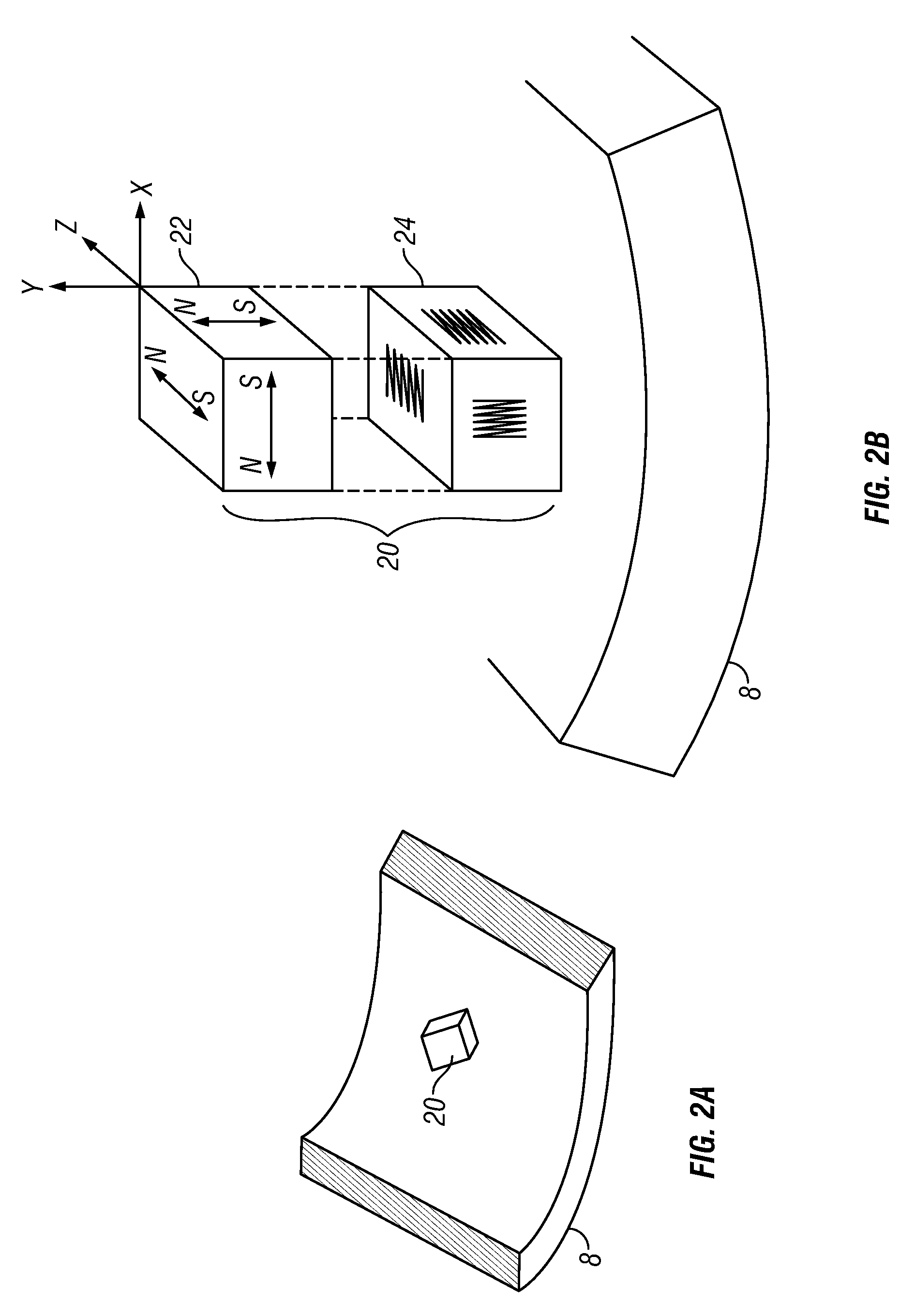
[0029] The present disclosure describes a combined electromagnetic acoustic transducer (EMAT) adapted to generate both shear horizontal type (SH-type) acoustic waves and Lamb-type acoustic waves in a conductive casing. The transducer comprises one magnet assembly and two radio frequency (RF) coils implemented as a multi-layer printed circuit board. Each coil is used to generate or receive acoustic signals of one wave type. Compared to using two single-wave-type transducers the combined one significantly reduces the total attraction force between the casing and the EMAT, and correspondingly simplifies the mechanical aspects of the measurement tool.

[0030] Lamb waves are complex vibrational waves that travel through the entire thickness of a material, such as a metal plate. While different modes of waveforms are possible with Lamb waves, two of the most common types of Lamb waves are symmetric and anti-symmetric. In a symmetric Lamb wave, particle movement within the plate undergoes b...


PUM


Abstract

A combined electromagnetic acoustic transducer (EMAT) is disclosed adapted to generate both SH-type acoustic waves and LAMB-type acoustic waves in a conductive casing, surroundings of which are to be analyzed. The transducer comprises one magnet assembly and two RF coils implemented as multi-layer printed circuit board. Each coil is used to generate or receive acoustic signals of one wave type. Compared to using two single-wave-type transducers the combined EMAT significantly reduces total attraction force to the casing and, correspondingly, simplifies mechanics of the measurement tool. It is emphasized that this abstract is provided to comply with the rules requiring an abstract which will allow a searcher or other reader to quickly ascertain the subject matter of the technical disclosure. It is submitted with the understanding that it will not be used to interpret or limit the scope or meaning of the claims.

Description

CROSS REFERENCE TO RELATED APPLICATIONS [0001] This patent application is a continuation-in-part of U.S. patent application Ser. No. 10 / 971,485 filed on Oct. 22, 2004, which is a continuation-in-part of U.S. patent application Ser. No. 10 / 802,612 filed on Mar. 17, 2004. This patent application is also a continuation-in-part of U.S. patent application Ser. No. 11 / 070,037 filed on Mar. 2, 2005.BACKGROUND OF THE DISCLOSURE [0002] 1. Field of the Invention [0003] The invention relates generally to the field evaluating the integrity of bonds that adhere wellbore casing to a wellbore. More specifically, the present invention relates to a method and apparatus of producing and detecting acoustic forces within a wellbore casing to evaluate the integrity of the casing. [0004] 2. Description of Related Art [0005] As illustrated in FIG. 1 wellbores typically comprise casing 8 set within the wellbore 5, where the casing 8 is bonded to the wellbore by adding cement 9 within the annulus formed bet...

Claims


Application Information

Patent Timeline
IPC IPC(8): G01V1/00
CPCB06B1/04E21B47/0005E21B47/16G01N29/2412G01N2291/011G01V1/44G01N2291/0422G01N2291/0427G01N2291/044G01N2291/2636G01N2291/015E21B47/005
Inventor REIDERMAN, ARCADYBAROLAK, JOSEPH G.
Owner BAKER HUGHES INC
Learn More