
Adjustable mounting bracket for feed buckets and the like

a technology of mounting brackets and feed buckets, which is applied in the field of adjustable mounting brackets, can solve the problems of inconvenient personal time for hobbyists, substantial manpower costs for professional horse breeders, and lethal conditions, and achieve the effects of convenient maintenance, effective sliding positioning, and effective preventing the handle of the feed bucket from disengaging

Inactive Publication Date: 2007-09-13
BROCK TED A +1
View PDF11 Cites 4 Cited by
  • Summary
  • Abstract
  • Description
  • Claims
  • Application Information

AI Technical Summary

Benefits of technology

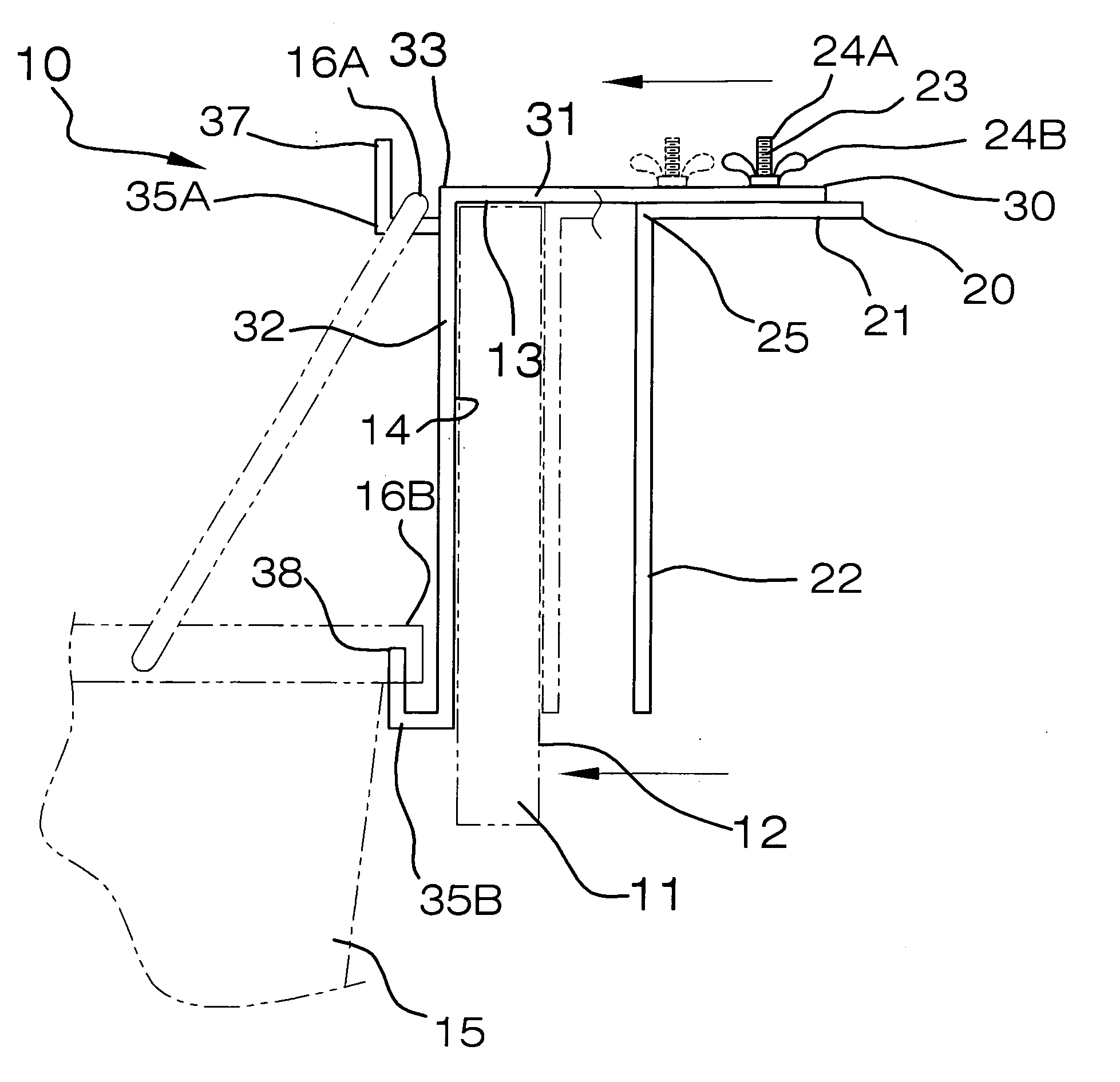
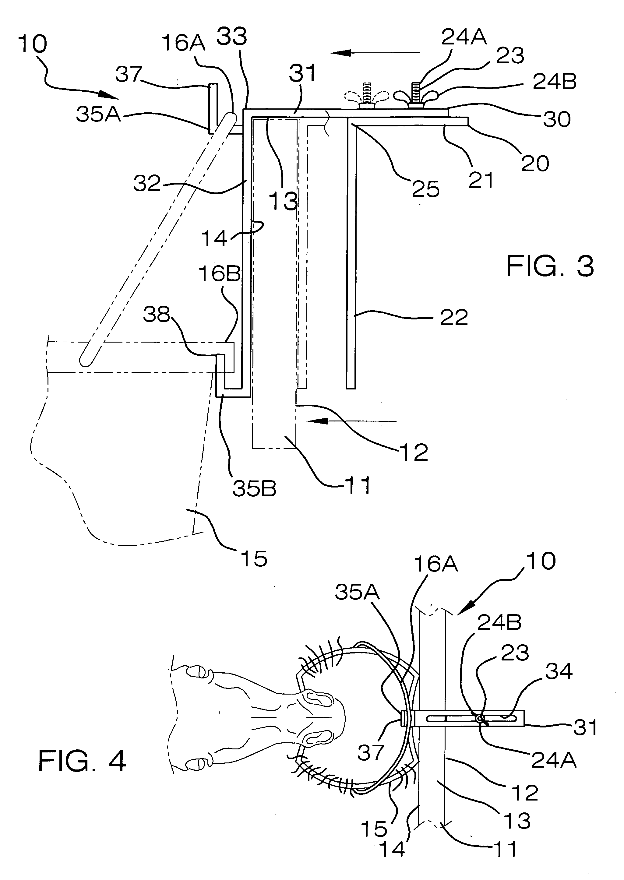
[0014] In alternate position, the 90 degree elbow of the first member is preferably firmly engaged directly against a top edge of the support post such that the first member horizontal portion traverses directly over the top edge and contiguously abuts thereagainst. At such a position, the second member horizontal portion is spaced above the top edge of the support post. The first member horizontal portion may have a longitudinal length that is shorter than a longitudinal length of the second member horizontal portion so that the support post can effectively be intercalated between the first and second member vertical portions respectively.
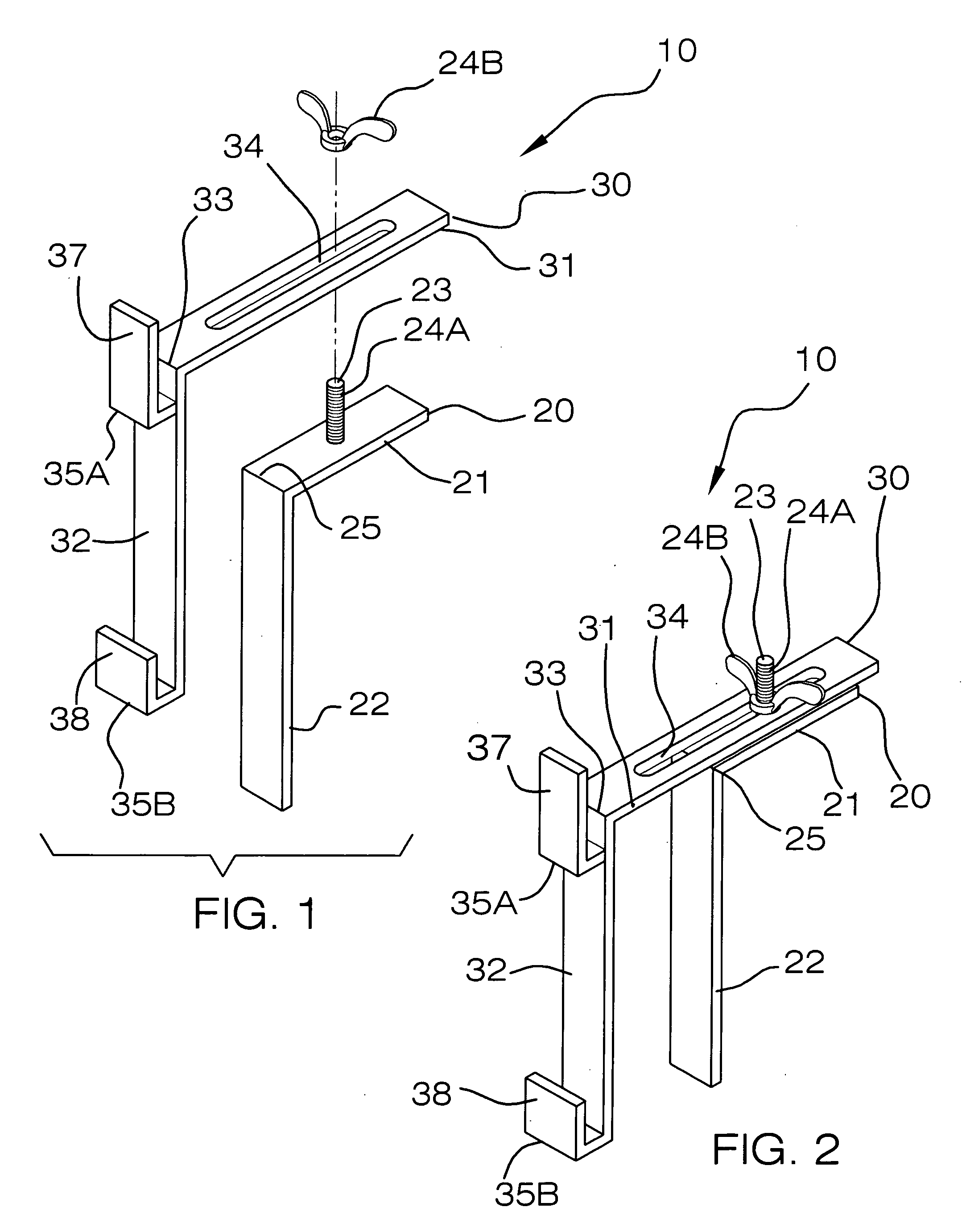
[0016] The second member horizontal portion has a linear slot formed therein in such a manner that the fastener assembly can advantageously and effectively be slidably positioned along a longitudinal length of the slot so that a user can adjustably adapt a spatial distance between the vertical portions of the first and second members and conveniently attach the mounting bracket to various sized support posts respectively.
[0017] A plurality of L-shaped fingers are monolithically formed with the second member and protrude forwardly away from the support post. Such L-shaped fingers receive first and second portions of the feed bucket in such a manner that the feed bucket is advantageously and conveniently maintained at a substantially static position during feeding procedures. One of the fingers may be disposed at a top end of the second member vertical portion and adjacent to the 90 degree elbow of the second member. Such one finger has a vertically oriented portion for advantageously and effectively preventing a handle of the feed bucket from disengaging the one finger during feeding procedures. Another one of the fingers is preferably monolithically formed with a bottom edge of the second member vertical portion and includes a vertical portion positioned upwardly and directly against an outer lip of the feed bucket for conveniently and effectively preventing the feed bucket from oscillating about the bucket handle during feeding procedures.

Problems solved by technology

This requires inconvenient personal time for the hobbyist and a substantial manpower cost for the professional horse breeder.
This condition may be lethal and at best is a serious illness.
The nature of the granular feed and the horses' eating habits typically spill a substantial amount of food on the ground.
This causes sand colic and results in the death of hundreds, if not thousands, of horses each year.
Such an apparatus includes a fenced in area with a fence section that does not allow the horse to stick its head through the fence to reach the ground on the outside of the fence section.
Unfortunately, such an apparatus has several draw backs.
This greatly limits the versatility of the apparatus for feeding horses that are located at remote locations form each other from the same apparatus.
Thus the owner must purchase multiple apparatuses, which can become quite expensive and labor intensive when installation time is taken into consideration.
A further disadvantage is that the apparatus is limited to suspending a bucket of one size only, thus not allowing the user to vary the amount of feed that a horse is consuming.

Method used


Image

  • Adjustable mounting bracket for feed buckets and the like
  • Adjustable mounting bracket for feed buckets and the like
  • Adjustable mounting bracket for feed buckets and the like

Examples


Embodiment Construction

[0026] The present invention will now be described more fully hereinafter with reference to the accompanying drawings, in which a preferred embodiment of the invention is shown. This invention may, however, be embodied in many different forms and should not be construed as limited to the embodiment set forth herein. Rather, this embodiment is provided so that this application will be thorough and complete, and will fully convey the true scope of the invention to those skilled in the art. Like numbers refer to like elements throughout the figures.

[0027] The apparatus of this invention is referred to generally in FIGS. 1-5 by the reference numeral 10 and is intended to provide an adjustable mounting bracket for feed buckets and the like. It should be understood that the apparatus 10 may be used to support many different types of items and should not be limited in use to only supporting support buckets from conventional support posts.

[0028] Referring initially to FIGS. 1, 2, 3 and 4,...


PUM


Abstract

A non-corrosive mounting bracket includes first and second members that have L-shapes and include horizontal and vertical portions defining a 90 degree elbow. The first member vertical portion is abutted against a post's rear surface and has a fastener assembly attached thereto. The fastener assembly includes a bolt and wing nut. The second member's vertical portion is abutted against the post's front surface, and the horizontal portion extends rearward along the post and travels parallel to the first member horizontal portion. The second member horizontal portion has a slot so that the fastener assembly is slidably positionable along the slot. L-shaped fingers are formed with the second member and protrude forwardly away from the post for receiving select portions of the feed bucket so that the bucket is maintained at a static position during feeding procedures.

Description

CROSS REFERENCE TO RELATED APPLICATIONS [0001] Not Applicable. STATEMENT REGARDING FEDERALLY SPONSORED RESEARCH OR DEVELOPMENT [0002] Not Applicable. REFERENCE TO A MICROFICHE APPENDIX [0003] Not Applicable. BACKGROUND OF THE INVENTION [0004] 1. Technical Field [0005] This invention relates to mounting brackets and, more particularly, to an adjustable mounting bracket for feed buckets and the like. [0006] 2. Prior Art [0007] The raising of horses is a major industry as well as a hobby or major avocation for many persons in the United States and around the world. The horses' life is spent mostly out of doors. Under the best of circumstances, when weather allows, the horse is most content when running free in a fenced in enclosure. It would be preferable for the horse to enter a building only to sleep at night. However, it is necessary, using present devices and methods, to bring the horses indoors when feeding. As a consequence, it is necessary for the owner or his agents to go outsi...

Claims


Application Information

Patent Timeline
Patent Type & Authority Applications(United States)
IPC IPC(8): A01K5/00
CPCA01K5/01
Inventor BROCK, TED A.BROCK, RONALD G.
Owner BROCK TED A
Learn More