
Dual stage energy absorber

a technology of energy absorption and bumpers, which is applied in the direction of bumpers, vehicle components, vehicular safety arrangements, etc., can solve the problems of not being able to meet all the global requirements with a single bumper system, the approach is often impractical and often impossible, and the design fails to meet the regulatory requirements of various countries

Inactive Publication Date: 2007-08-30
GENERAL ELECTRIC CO
View PDF3 Cites 42 Cited by
  • Summary
  • Abstract
  • Description
  • Claims
  • Application Information

AI Technical Summary

Benefits of technology

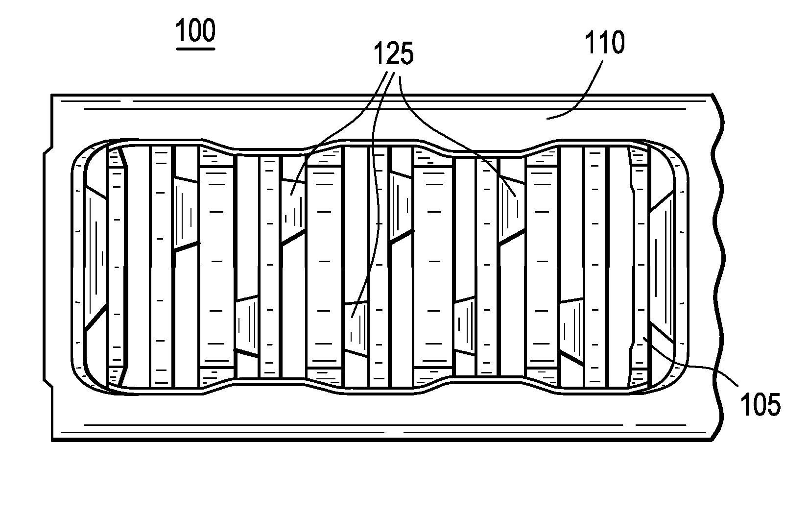
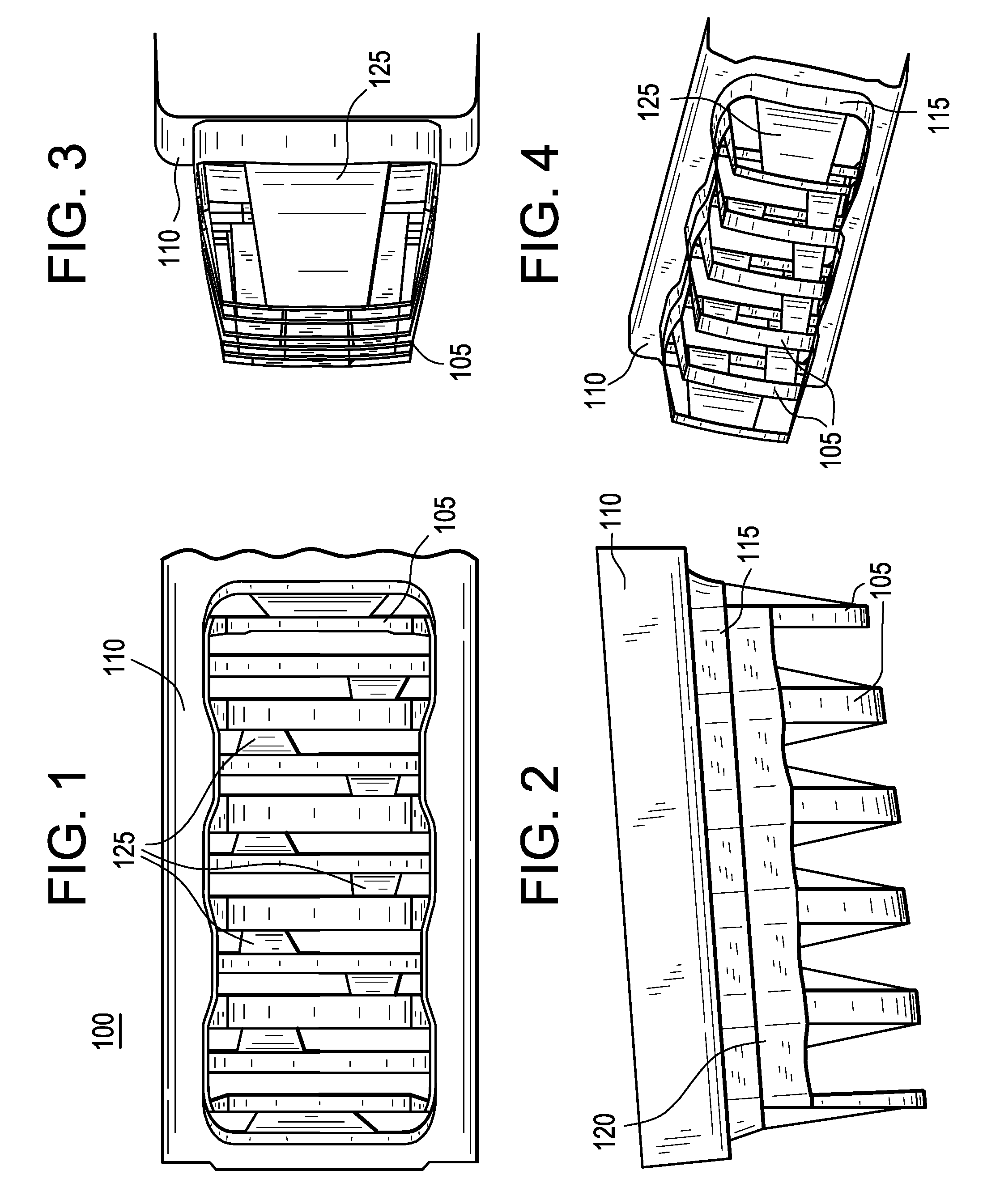
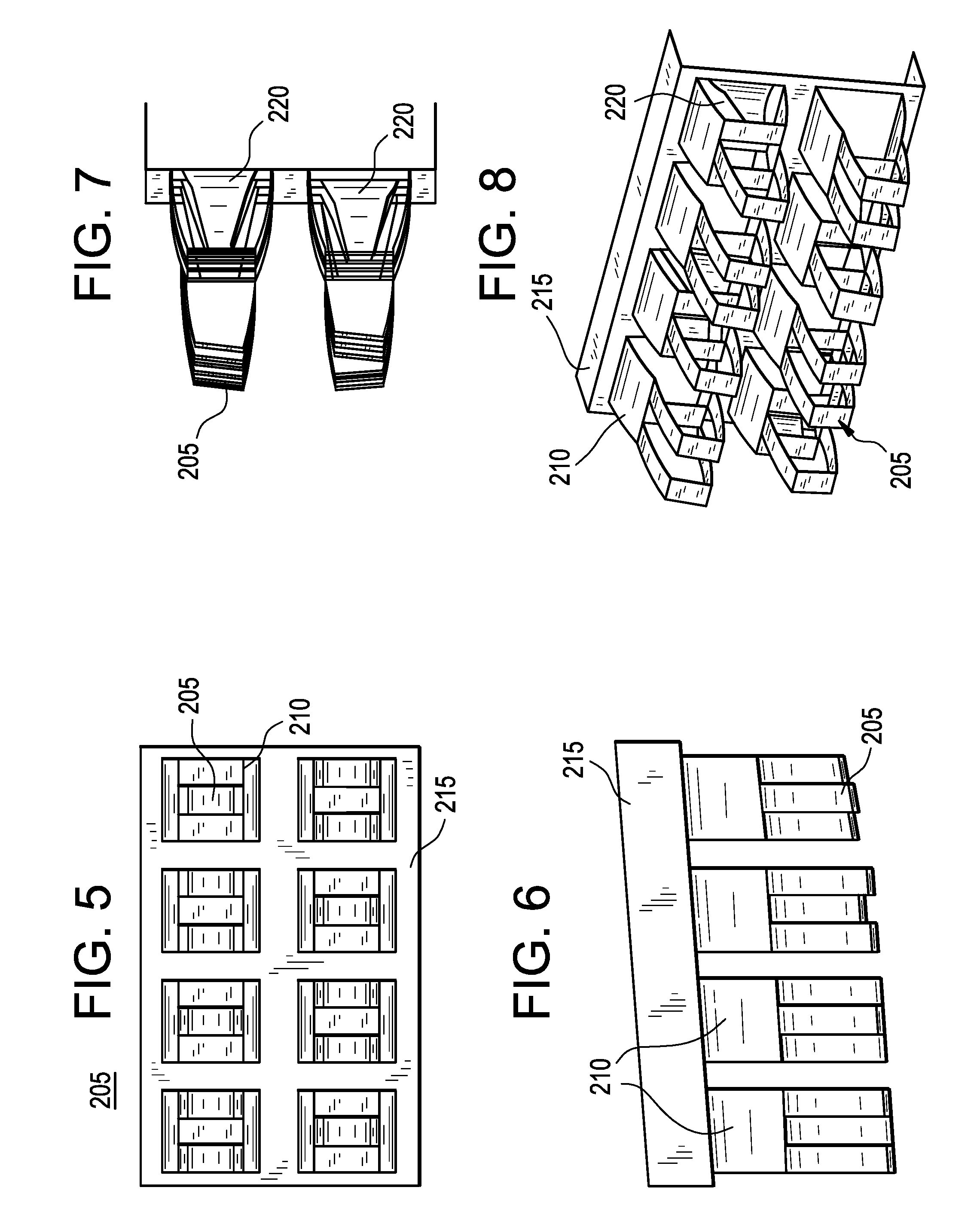
[0006] The present invention addresses the issues associated with prior art bumper systems by using a dual stage energy absorption bumper system that includes one or more unique geometry configurations that extend “softer” energy absorbing surfaces forward in the system while nesting more “rigid” energy absorbing surfaces more rearward only to come into effect when higher energy impacts are observed. The dual energy absorption may be achieved using a number of configurations and / or methods or a combination of several. In one or more embodiments, the wall thickness of the material used in the component or components may be varied, materials having different stiffness properties may be used, and / or geometries of different depth and section stiffness may be alternated across the bumper system.

Problems solved by technology

Since several of the various region requirements conflict, no system has been designed that is capable of meeting all the global requirements with a single bumper system.
However, this approach is very impractical and often impossible due to the styling requirements of current automobiles.
In addition, while many automobiles have their own designs for absorbing the force and energy associated with a collision, such as crumple zones, many of these designs fail to satisfy the regulatory requirements of various countries.
Nevertheless, damage may also be sustained in low-impact collisions.
While many automobiles do include designs selected to help protect the vehicle during low impact collisions, these designs do not take into account the possible damage to the object struck.

Method used


Image

  • Dual stage energy absorber
  • Dual stage energy absorber
  • Dual stage energy absorber

Examples


Embodiment Construction

[0021] The present invention is more particularly described in the following description and examples that are intended to be illustrative only since numerous modifications and variations therein will be apparent to those skilled in the art. As used in the specification and in the claims, the singular form “a,”“an,” and “the” may include plural referents unless the context clearly dictates otherwise. Also, as used in the specification and in the claims, the term “comprising” may include the embodiments “consisting of” and “consisting essentially of.” Furthermore, all ranges disclosed herein are inclusive of the endpoints and are independently combinable.

[0022] As used herein, approximating language may be applied to modify any quantitative representation that may vary without resulting in a change in the basic function to which it is related. Accordingly, a value modified by a term or terms, such as “about” and “substantially,” may not to be limited to the precise value specified, ...


PUM


Abstract

A motor vehicle bumper that has enhanced energy absorption characteristics and that includes one or more unique geometry configurations that extend “softer” energy absorbing surfaces forward in the system while nesting more “rigid” energy absorbing surfaces more rearward only to come into effect when higher energy impacts are observed. The dual energy absorption may be achieved using a number of configurations and / or methods or a combination of several. In one or more embodiments, the wall thickness of the material used in the component or components may be varied, materials having different stiffness properties may be used, and / or geometries of different depth and section stiffness may be alternated across the bumper system.

Description

CROSS REFERENCE TO RELATED APPLICATION [0001] This application claims priority to U.S. Provisional Application No. 60 / 774,259, which was filed Feb. 16, 2006.FIELD OF INVENTION [0002] The present invention relates to motor vehicle components and, in particular, to motor vehicle bumpers capable of absorbing impact energy. BACKGROUND OF INVENTION [0003] In the current automotive environment, vehicles that are exported to other global regions must be designed appropriately to meet different regulatory requirements for the various vehicle systems. As a result most vehicles for export require a different bumper system to meet the specific requirements of the region to which they are exported. This usually requires multiple bumper components for the same vehicle so that a different bumper system can be assembled for the specific region destination. This requires additional investment for tooling, equipment, labor, assembly space, etc. Since several of the various region requirements confli...

Claims


Application Information

Patent Timeline
IPC IPC(8): B60R19/03
CPCB60R19/18B60R2019/1893B60R2019/1833B60R19/24
Inventor JAARDA, ERIC JONMAHFET, MICHAEL R.MOHAPATRA, SUBHRANSUNAGWANSHI, DHANENDRA KUMARRAMANI, SREERAM TIRUNELLAI
Owner GENERAL ELECTRIC CO
Learn More