Eureka AIR delivers breakthrough ideas for toughest innovation challenges, trusted by R&D personnel around the world.

Hydraulic drive arrangement for the cutter of a pull-type crop harvesting machine

a technology of hydraulic drive and pull-type crop harvesting machine, which is applied in the direction of towing device, agricultural machine, mower, etc., can solve the problems of complex device, no commercial success, and reduced manoeuvrability

Inactive Publication Date: 2007-08-30
MACDON INDS
View PDF8 Cites 21 Cited by
  • Summary
  • Abstract
  • Description
  • Claims
  • Application Information

AI Technical Summary

Benefits of technology

The invention is a pull-type crop harvesting machine that is towed by a tractor. It includes a frame that carries a cutter system for cutting the crop and a hitch arm for attachment to the tractor. The machine has a hydraulic circuit for driving the cutter system and a mechanical drive connection for the tractor. The frame has a transverse frame member that supports the frame in movement across ground wheels and a transverse cutter support bar that supports the cutting system. The machine also has a cooling system for the hydraulic fluid. The technical effects of the invention include improved machine performance, better cooling of the hydraulic fluid, and increased efficiency of the hydraulic circuit.

Problems solved by technology

This arrangement has however a number of disadvantages in that different designs are provided for the draw bar construction and for the three point hitch construction and of course it is highly desirable that a common design is provided.
Furthermore the arrangement locates the pump at a forward position which reduces the length of the connecting shaft which can be connected between the pump and the PTO shaft which thus reduces manoeuvrability.
This construction provides a complex device for towing equipment in a row one behind the-other which has achieved no commercial success.

Method used


Image

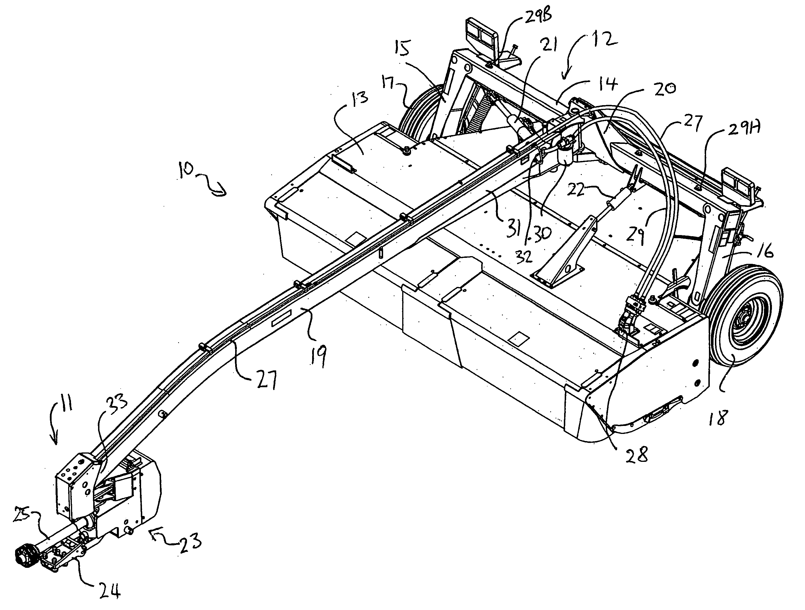
  • Hydraulic drive arrangement for the cutter of a pull-type crop harvesting machine
  • Hydraulic drive arrangement for the cutter of a pull-type crop harvesting machine
  • Hydraulic drive arrangement for the cutter of a pull-type crop harvesting machine

Examples


Embodiment Construction

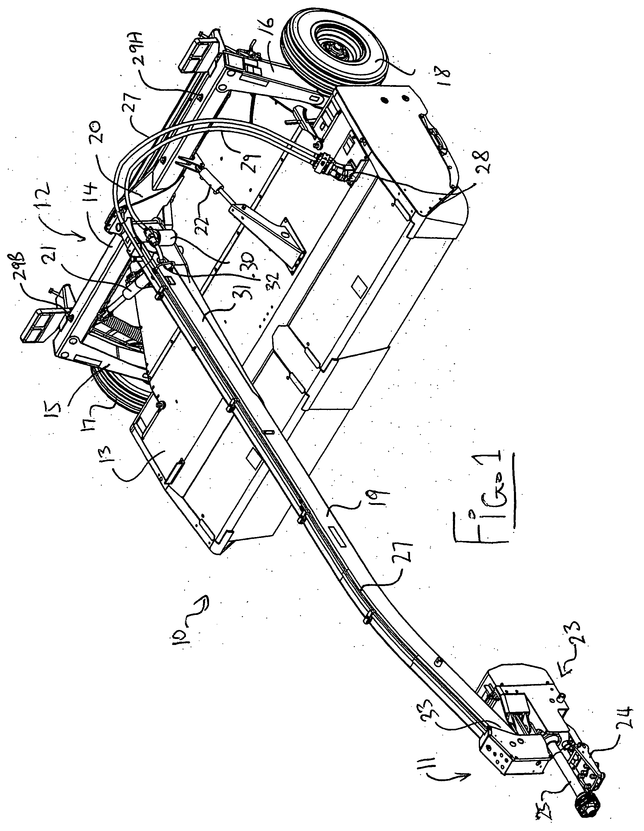
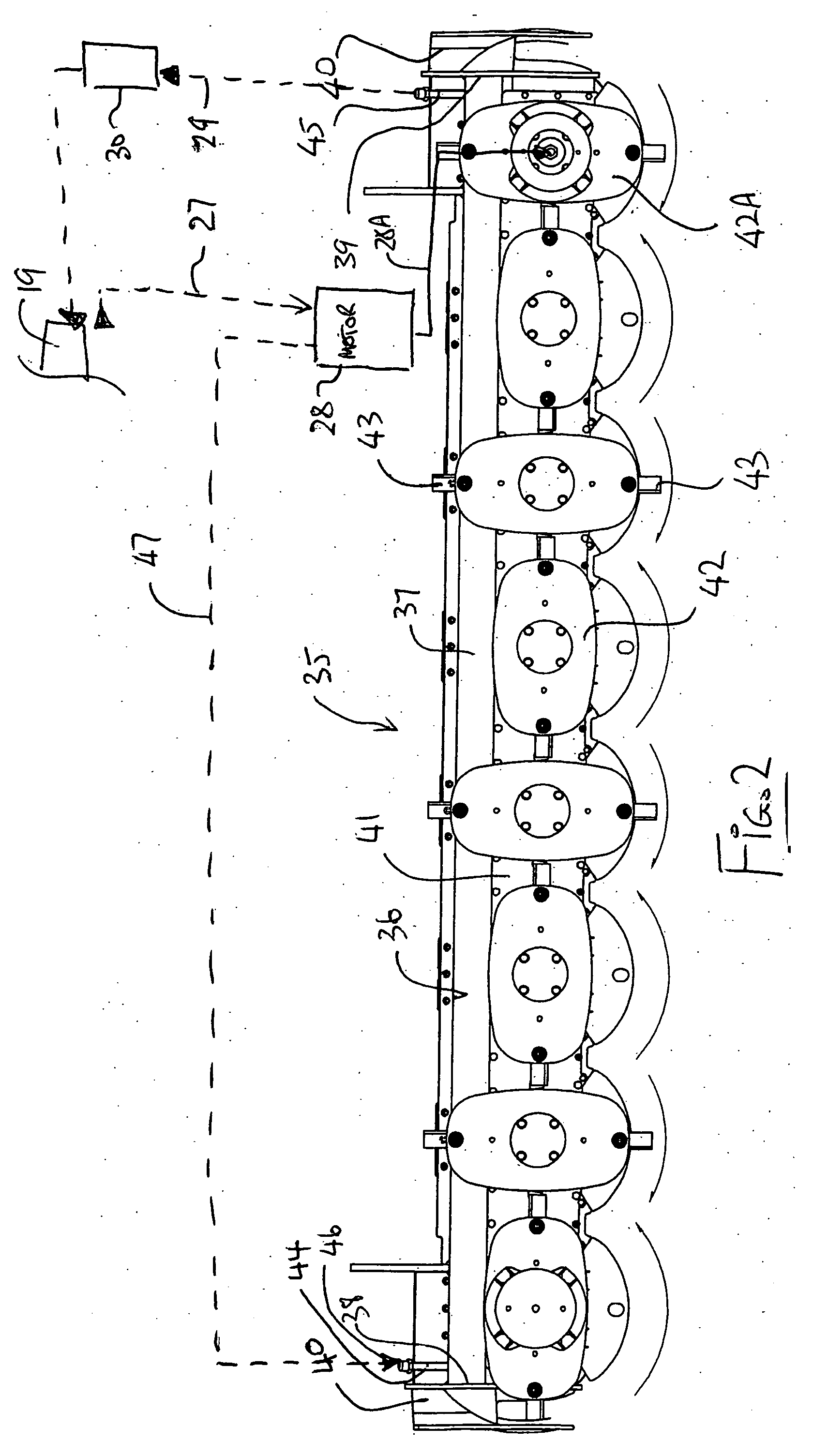
[0057] In FIG. 1 is shown a pull type harvesting machine generally indicated at 10 for attachment to a tractor (not shown) by a hitch coupling generally indicated at 11. The crop harvesting machine shown is of the type which uses a row of discs mounted on a cutter bar as shown in FIG. 2. Thus each disc is mounted on the cutter bar for rotation about its own axis with the axes spaced positions across the width of the cutter bar and when the axes generally vertical. Each disc carry blades at 180° spacing so that one disc rotate 90° out of phase with the next adjacent disc thus allowing the cutting action of the blades to overlap. Arrangements of this type are well known and many examples can be found in the prior art. The cutter bar of FIG. 2 is mounted on a frame generally indicated at 12 and is covered by a housing generally indicated at 13 so that the cutter system is enclosed for safety.

[0058] The frame 12 includes a transverse beam 14 which extends across the width of the harves...


PUM


Abstract

A pull-type crop harvesting machine has disk cutter carried on a frame mounted on ground wheels with a hitch arm extending from the frame over the header to a hitch connector of a tractor. The hitch arm is mounted for pivotal movement about a generally upright axis such that in a first position the tractor tows the frame in echelon to one side and in a second position the tractor tows the frame in echelon. The disks are hydraulically driven by a pump at the front end of the hitch arm and a motor at the frame with the hydraulic circuit including a sump tank defined by a hollow interior of the hitch arm and a cooling radiator defined by a tubular frame member which is preferably located at the disk drive as a support therefore as it is cooled by the air flow from the disks and contact with the crop and carries a low volume of fluid.

Description

[0001] This invention relates to a pull-type crop harvesting machine of the type including a header carried on a frame to be towed behind a tractor and particularly to an improvement relating to the hydraulic drive to the cutter system. [0002] Pull-type harvesting machines are towed from the tractor by a hitch arm which requires to be adjusted in angle relative to the frame of the machine for fine steering movements and more coarse movement to the transport position. [0003] Some machines are required to follow the tractor only to one side and thus include a hitch arm which is located at one end of the machine. In others in which the present invention is particularly effective, the hitch arm to the tractor extends from the frame over the header to a hitch coupling and can be swung by an operating cylinder from one side of the header to the other so that the header can be located in echelon with the tractor to one side of symmetrically to the other side. [0004] Pull-type harvesting ma...

Claims


Application Information

Patent Timeline
Patent Type & Authority Applications(United States)
IPC IPC(8): A01D69/00
CPCA01B59/042A01D69/03A01B71/06
Inventor BARNETT, NEIL GORDON
Owner MACDON INDS
Why Eureka
Eureka Blog
Learn More