Image forming device

a technology of forming device and image, which is applied in the direction of instruments, electrographic process apparatus, optics, etc., can solve the problems of changing the sensor output of magnetic sensors, unable to develop devices, and unable to replenish toner, etc., and achieves the effect of stable sensor output characteristic valu

Active Publication Date: 2007-08-23
KYOCERA DOCUMENT SOLUTIONS INC
View PDF2 Cites 24 Cited by
  • Summary
  • Abstract
  • Description
  • Claims
  • Application Information

AI Technical Summary

Benefits of technology

[0011]It is an object of the present invention to provide an image forming device that is capable of obtaining a stable sensor output characteristic value from the sensor output of the toner concentration sensor, even when the characteristics of the developer are varied, or the toner concentration is varied.

Problems solved by technology

The method is not valid for developing devices with the commonly-used screw-shaped agitation member.
This also results in a change in the sensor output of the magnetic sensors.
Therefore, using the average value of sensor output as the sensor characteristic output value to control the replenishment of toner does not achieve a stable toner concentration.

Method used


Image

  • Image forming device
  • Image forming device
  • Image forming device

Examples


Embodiment Construction

[0025]Selected embodiments of the present invention will now be explained with reference to the drawings. It will be apparent to those skilled in the art from this disclosure that the following descriptions of the embodiments of the present invention are provided for illustration only and not for the purpose of limiting the invention as defined by the appended claims and their equivalents.

[0026]The following is an explanation of the embodiments of the present invention with reference to the drawings for the case of application to a photocopier.

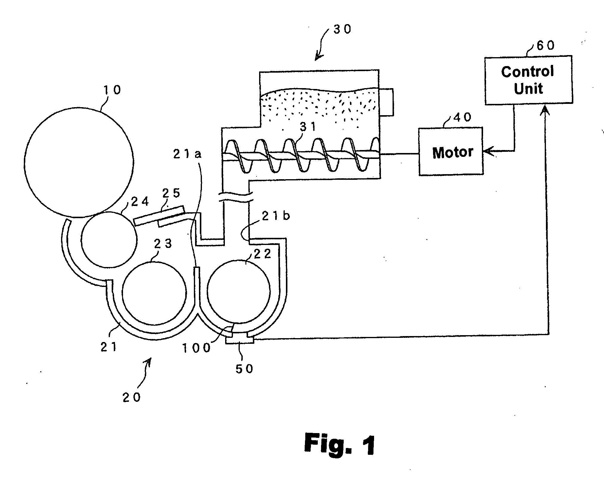
[0027]FIG. 1 is a diagrammatical view showing a photosensitive drum and a developing device within a photocopier in accordance with a preferred embodiment of the present invention.

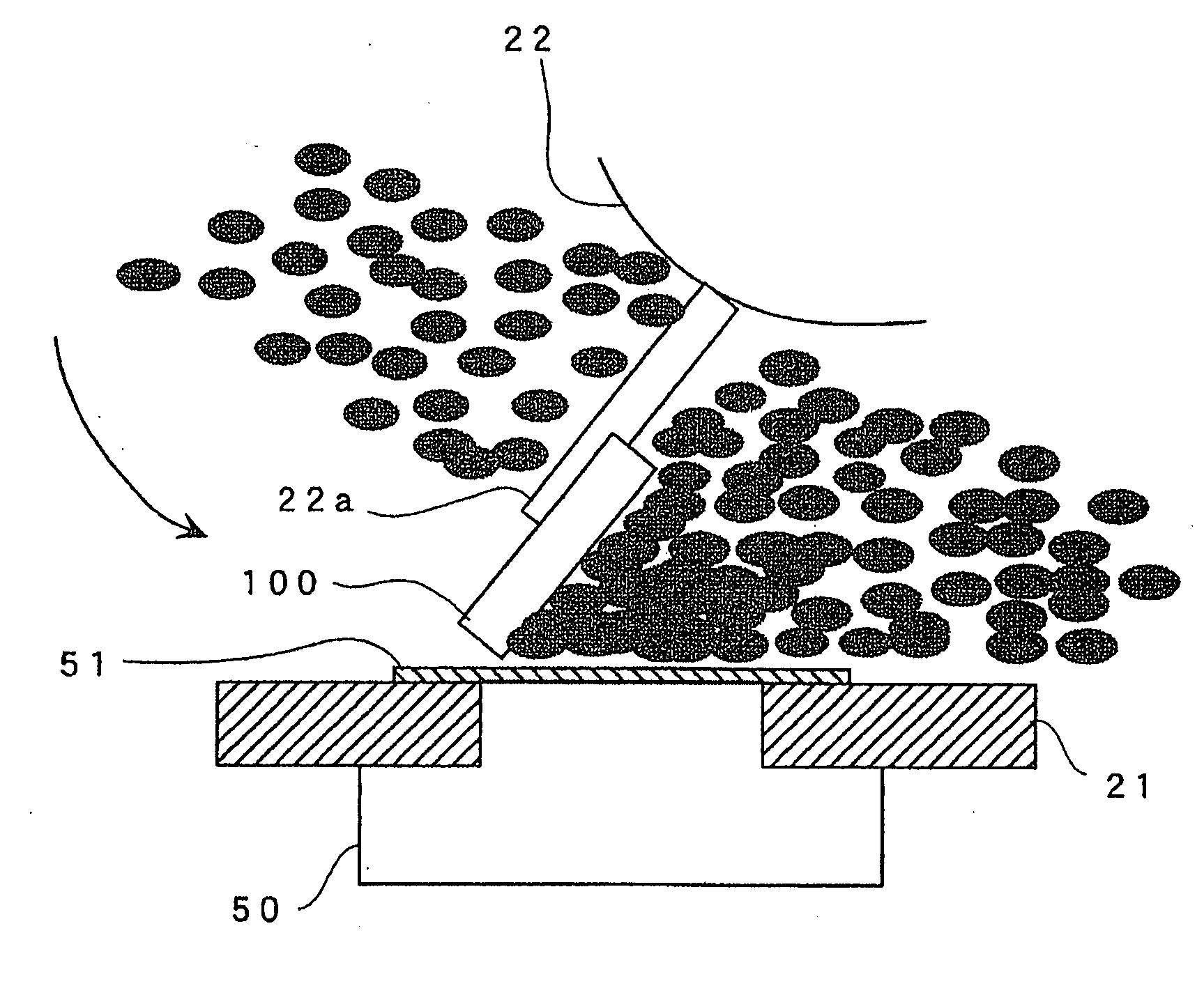
[0028]In FIG. 1, 10 is a photosensitive drum (image carrier), and 20 is a developing device that develops electrostatic latent images formed on the photosensitive drum 10 using toner.

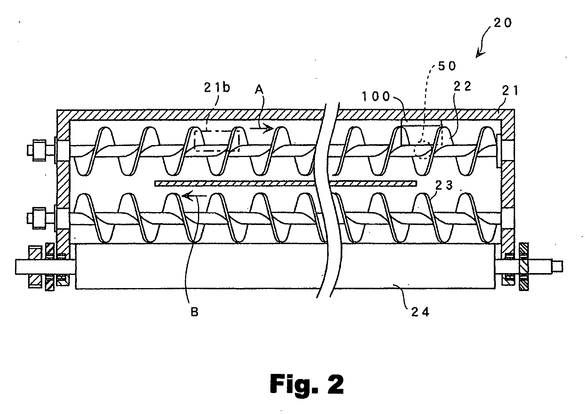
[0029]As shown in FIGS. 1 and 2, the developing device 20 includes a housing 21 that...


PUM


Abstract

A developer agitation screw is provided with a blade to gather developer onto the sensor surface of a toner concentration sensor. A toner concentration control unit detects the maximum value of the output of the toner concentration sensor within each predetermined period of time, the predetermined period of time being longer than the period in which developer is gathered on the sensor surface of the toner concentration sensor by the blade. The obtained maximum value is used as a characteristic value to control the toner concentration.

Description

CROSS-REFERENCE TO RELATED APPLICATIONS[0001]This application claims priority to Japanese Patent Application No. 2006-042909 filed on Feb. 20, 2006. The entire disclosure of Japanese Patent Application No. 2006-042909 is hereby incorporated herein by reference.BACKGROUND OF THE INVENTION[0002]1. Field of the Invention[0003]The present invention generally relates to an image forming device. More specifically, the present invention relates to an image forming device such as a photocopier, printer, or the like.[0004]2. Background Information[0005]Normally in an image forming device, an electrostatic latent image is formed on a photosensitive drum, which is the image carrier. This electrostatic latent image is developed in a developing device to become a toner image. The toner image on the photosensitive drum is transferred onto a recording sheet. Then the toner image that is transferred onto the recording sheet is fixed onto the recording sheet by a fixing device.[0006]Some developing ...

Claims


Application Information

Patent Timeline
Patent Type & Authority Applications(United States)
IPC IPC(8): G03G15/08
CPCG03G2215/0897G03G15/0853G03G15/0893
Inventor WATANABE, AKIHIRO
Owner KYOCERA DOCUMENT SOLUTIONS INC
Why Eureka
Try Eureka