Supporting Mechanism Of Reflector And Projection Apparatus
a technology of projection apparatus and support mechanism, which is applied in the direction of projectors, mountings, instruments, etc., can solve the problems of large distortion in the output image of the projector, and achieve the effects of preventing the occurrence of large distortion in the optical image projected by the projection apparatus, reducing costs, and minimizing the shape of the reflection surface of the reflector
- Summary
- Abstract
- Description
- Claims
- Application Information
AI Technical Summary
Benefits of technology
Problems solved by technology
Method used
Image
Examples
embodiment 1
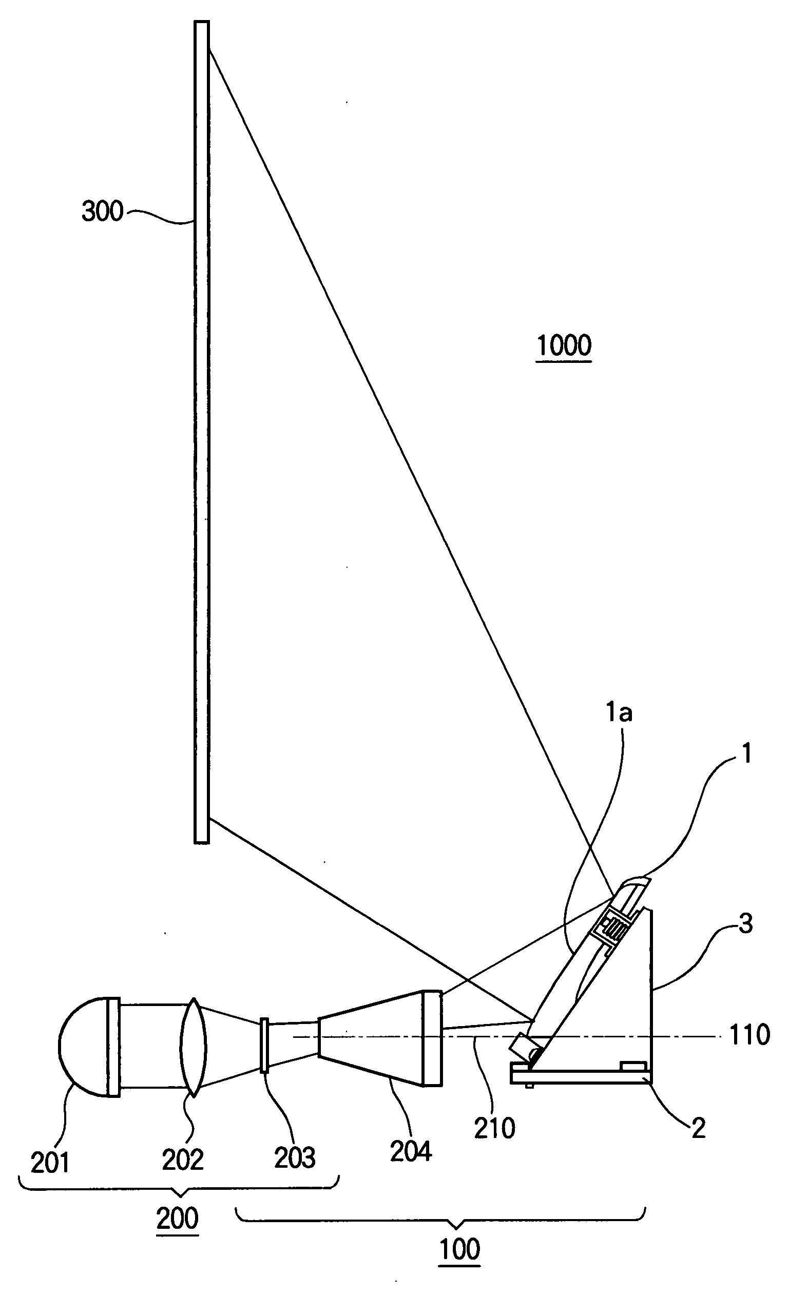
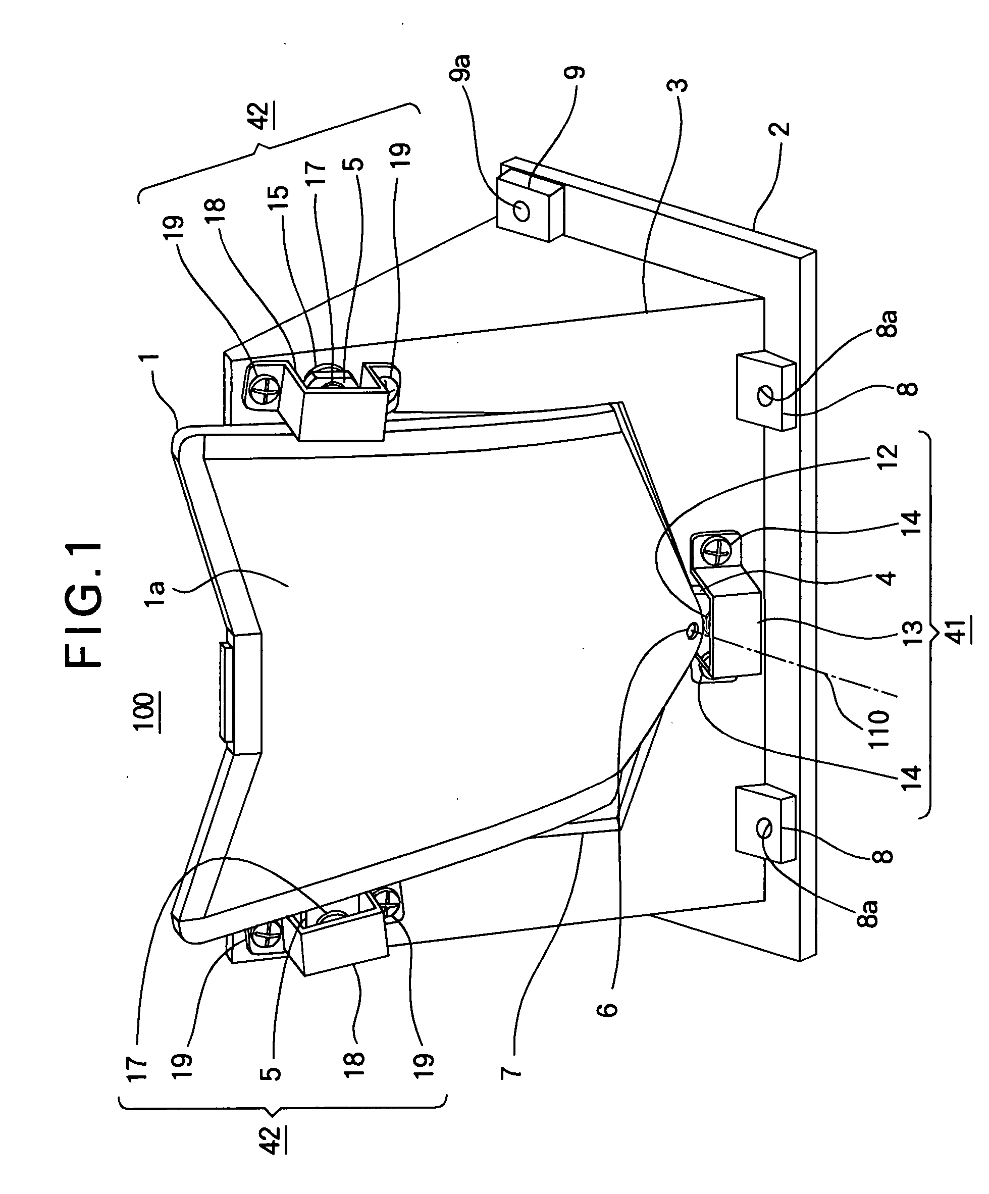
[0026] Hereinafter, Embodiment 1 of the present invention will be described with reference to the drawings. FIG. 1 is a perspective view of a supporting mechanism of a mirror (reflector) 1 according to Embodiment 1 of the present invention. FIG. 2 is a perspective view of a projector including a projection apparatus having the supporting mechanism of the mirror according to Embodiment 1. FIG. 3 is a perspective view of the mirror according to Embodiment 1. FIG. 4 is a side view of the mirror according to Embodiment 1. FIG. 5 is a side view showing the supporting mechanism of the mirror according to Embodiment 1 in an exploded manner. FIG. 6 is a cross-sectional view of a pivot supporting portion of the supporting mechanism of the mirror according to Embodiment 1. FIG. 7(A) is a longitudinal sectional view of a slide supporting portion of the supporting mechanism of the reflector according to Embodiment 1. In FIGS. 1 through 7, the same components are assigned the same reference nume...
embodiment 2
[0048] In the above described Embodiment 1, as was described with reference to FIG. 7(A), the slide supporting portion 42 is provided with the adjusting mechanism for adjusting the supporting position of the mirror (i.e., the reflector) 1. More specifically, the adjusting screw 16 is constructed by the member having the end portion 16b contacting the end portion 15b of the contact pin 15, and the adjusting screw 16 engages the fixing member 3, so that the supporting position of the mirror 1 can be adjusted by rotating the adjusting screw 16. In this Embodiment, the same adjusting mechanism is provided on the pivot supporting portion 41, so as to obtain the same advantage. More specifically, as shown in FIG. 7(B), an adjusting screw 11b (which is the same as the above described adjusting screw 16) constitutes the receiving portion 11 having a bowl-shaped receiving surface 11a contacting the end portion 10b of the pivot pin 10, and the adjusting screw 11b engages the threaded hole of ...
embodiment 3
[0049] Hereinafter, Embodiment 3 of the present invention will be described with reference to drawings. FIG. 8 is a cross-sectional view cut in the horizontal direction and as seen from below, showing a supporting mechanism of a pivot supporting portion 43 supporting the first lug 4 in this Embodiment. The supporting mechanism of the pivot supporting portion 43 has the configuration that differs from the supporting mechanism of the pivot supporting portion 41 (FIG. 6) described in Embodiment 1. FIG. 9 is a longitudinal sectional view cut in the horizontal direction and as seen from the side, showing a supporting mechanism of the slide supporting portions 42. The supporting mechanism of the slide supporting portions 42 has the configuration that differs from the supporting mechanism of the slide supporting portions 42 (FIG. 7) described in Embodiment 1. In respective parts shown in FIGS. 8 and 9, respective portions that are the same as or corresponding to the portions shown in FIGS....
PUM
 Abstract
Description
Claims
Application Information
 - R&D
- Intellectual Property
- Life Sciences
- Materials
- Tech Scout
- Unparalleled Data Quality
- Higher Quality Content
- 60% Fewer Hallucinations
Browse by: Latest US Patents, China's latest patents, Technical Efficacy Thesaurus, Application Domain, Technology Topic, Popular Technical Reports.
© 2025 PatSnap. All rights reserved.Legal|Privacy policy|Modern Slavery Act Transparency Statement|Sitemap|About US| Contact US: help@patsnap.com


