Imaging lens system
a technology of imaging lens and lens frame, which is applied in the field of imaging lens system, can solve the problems of insufficiently meeting the high picture quality and high resolution required for imaging lens system in these days, and the conventional lens system is not yet sufficient to meet the demands, size and weight, and achieve the effect of improving telecentricity and effectively correcting astigmatism in the periphery
- Summary
- Abstract
- Description
- Claims
- Application Information
AI Technical Summary
Benefits of technology
Problems solved by technology
Method used
Image
Examples
examples
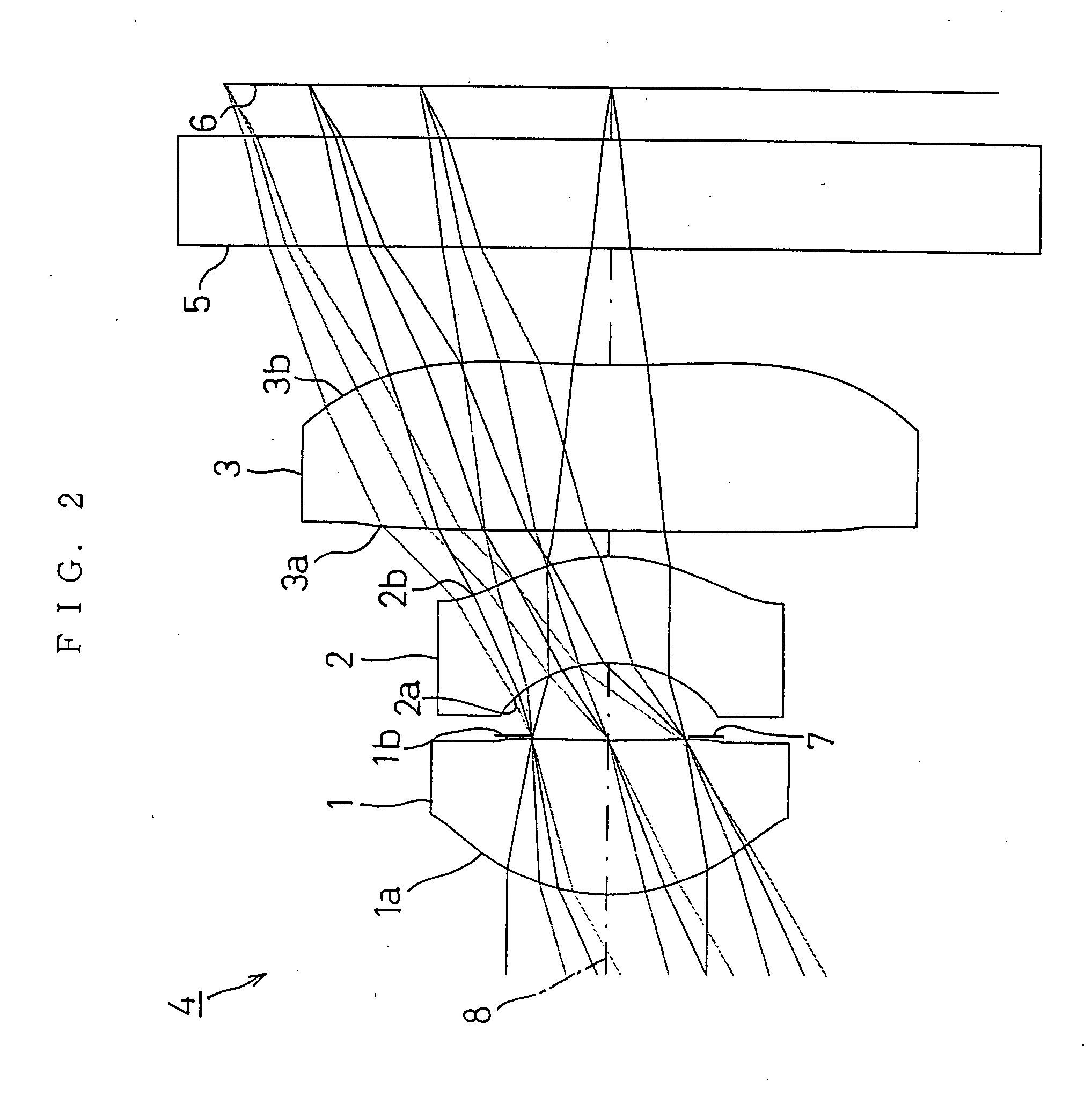
[0091] Next, EXAMPLES of the present invention will be described by referring to FIG. 2 to FIG. 25.
[0092] In EXAMPLES, F no denotes F-number, ω denotes a half angle of view, and r denotes the radius of center curvature. Further, d denotes the distance to the next optical surface, nd denotes the index of refraction against the d line and ν d denotes the Abbe number (d line being the reference).
[0093] k, A, B, C, and D denote each coefficient in a following expression (8). In other words, the shape of the aspherical surface is expressed by the following expression provided that the optical axial 8 direction is the Z axis, the direction orthogonal to the optical axis 8 (the height direction) is the X axis, the traveling direction of light is positive, k is the constant of cone, A, B, C, D are the aspherical coefficients, and r is the radius of center curvature;
ti Z(X)=r−1X2 / [1+{1−(k+1)r−2X2}1 / 2]+AX4+BX6+CX8+DX10 (8)
first example
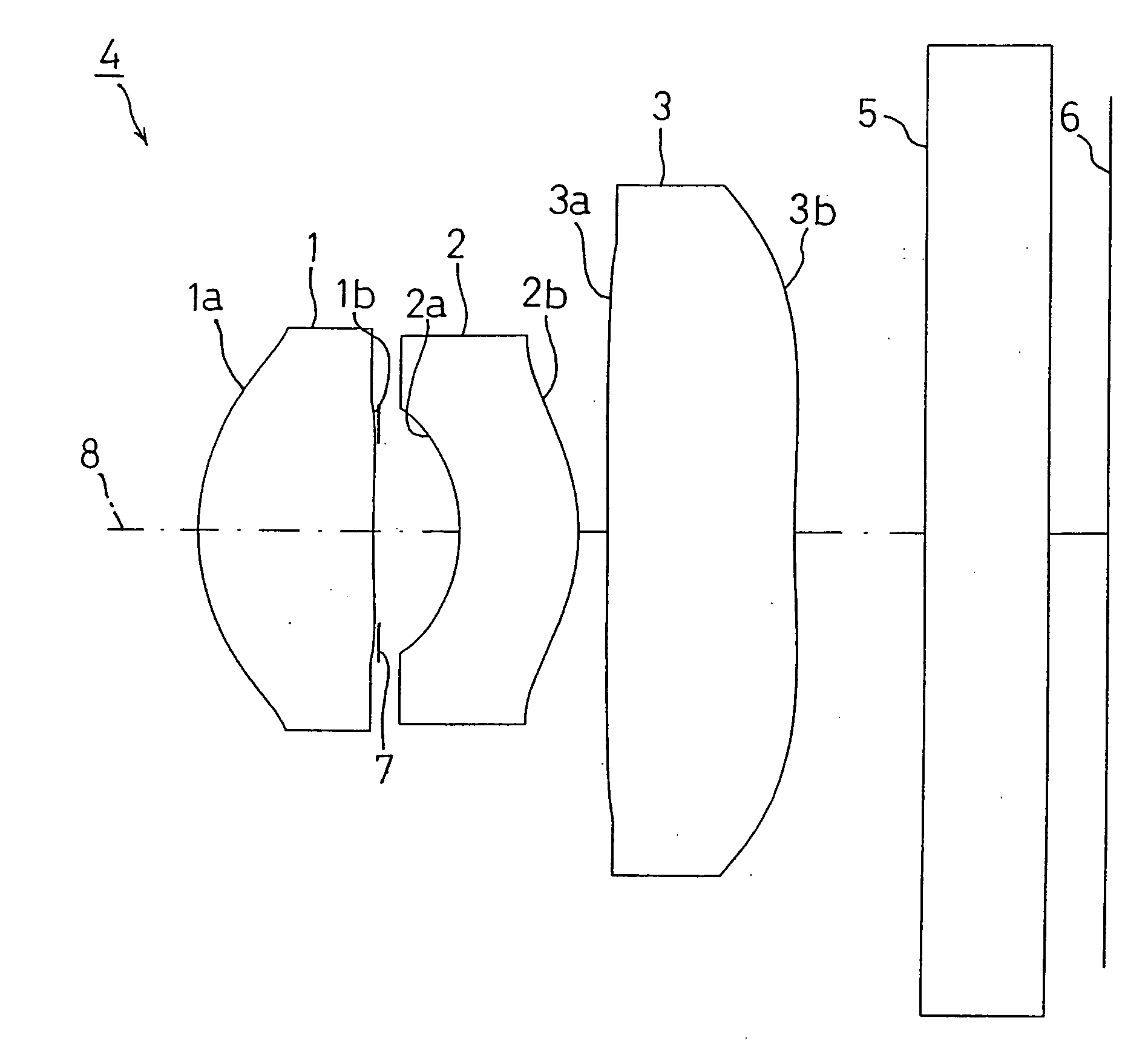
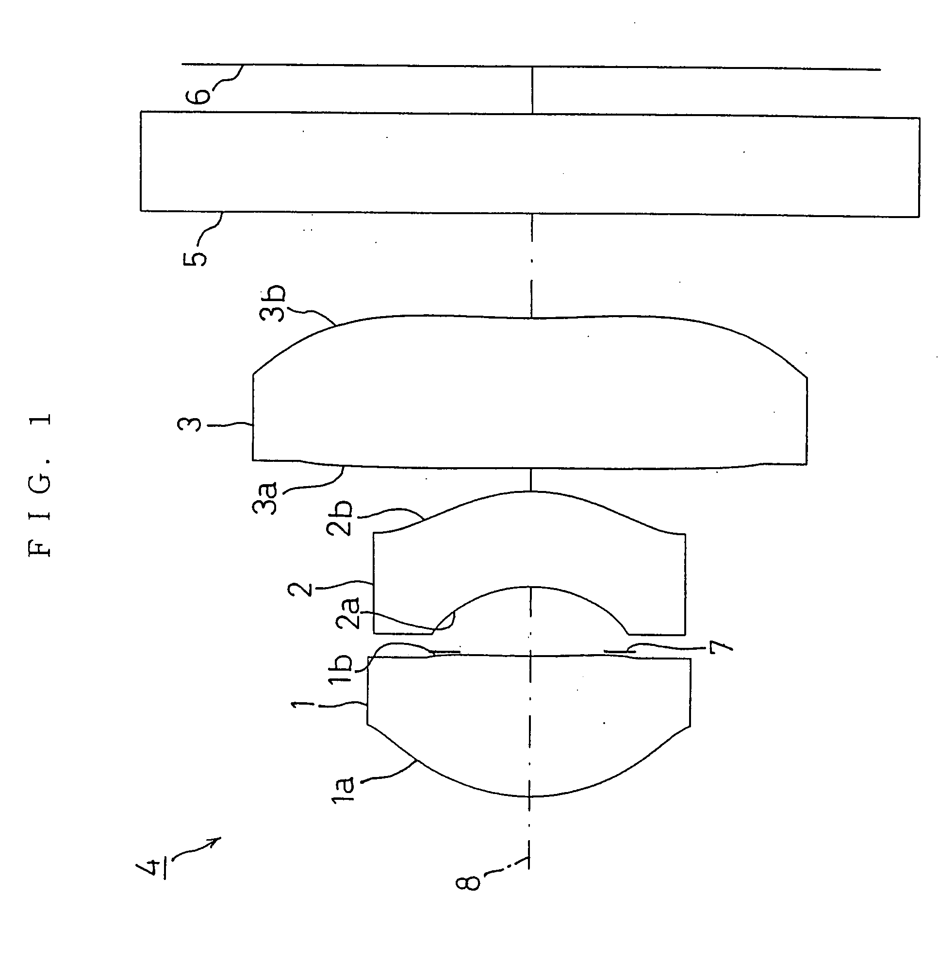
[0094]FIG. 2 shows FIRST EXAMPLE of the present invention. In FIRST EXAMPLE, an imaging lens system 4 shown in FIG. 2 was in the same configuration as that of the imaging lens system 4 shown in FIG. 1 and a diaphragm 7 was disposed between the first lens 1 and the second lens 2. The diaphragm 7 was regarded as the same surface as the second face 1b 2a of the first lens 2. Each of the first to third lenses 1, 2, 3 was formed using a resin material.
[0095] The imaging lens system 4 of FIRST EXAMPLE was set under the following conditions.
(Lens Data)f = 5.00 mm, F no = 3.18, ω = 30.99°Face Numberrdndνd(Object Point)∞1000.001 (First Face of First Lens)1.672071.2001.530055.82 (Second Face of First Lens) (Diaphragm)10.959950.5903 (First Face of Second Lens)−1.159540.8201.607027.04 (Second Face of Second Lens)−1.417950.2005 (First Face of Third Lens)−33.105551.2701.530055.86 (Second Face of Third Lens)9.073250.9007 (First Face of Cover Glass)∞0.8501.516864.28 (Second Face of Cover Glass)∞...
second example
[0100]FIG. 5 shows SECOND EXAMPLE of the present invention. In the imaging lens system 4 shown in FIG. 5, the diaphragm 7 was also regarded as the same surface as the second face 1b of the first lens 1. Each of the first to third lenses 1, 2, 3 was formed using a resin material.
[0101] The imaging lens system 4 of SECOND EXAMPLE was set under the following conditions.
(Lens Data)f = 5.00 mm, F no = 3.18, ω = 31.04°Face Numberrdndνd(Object Point)∞1000.3901 (First Face of First Lens)2.281501.0611.530055.82 (Second Face of First Lens) (Diaphragm)−5.909600.6493 (First Face of Second Lens)−1.091630.8001.607027.04 (Second Face of Second Lens)−1.485310.6025 (First Face of Third Lens)11.917780.9631.530055.86 (Second Face of Third Lens)4.250000.9007 (First Face of Cover Glass)∞0.8501.516864.28 (Second Face of Cover Glass)∞0.400(Image Surface)∞Face No.kABCD1−11.4164370.985518e−01−0.920520e−010.470655e−01−0.218362e−0120.000000−0.541953e−01−0.190726e−010.000000e+000.000000e+003−0.1625640.11076...
PUM
 Abstract
Description
Claims
Application Information
 - R&D
- Intellectual Property
- Life Sciences
- Materials
- Tech Scout
- Unparalleled Data Quality
- Higher Quality Content
- 60% Fewer Hallucinations
Browse by: Latest US Patents, China's latest patents, Technical Efficacy Thesaurus, Application Domain, Technology Topic, Popular Technical Reports.
© 2025 PatSnap. All rights reserved.Legal|Privacy policy|Modern Slavery Act Transparency Statement|Sitemap|About US| Contact US: help@patsnap.com


