
Liquid Crystal Display Device

Inactive Publication Date: 2007-08-23
KONINKLIJKE PHILIPS ELECTRONICS NV
View PDF5 Cites 3 Cited by
  • Summary
  • Abstract
  • Description
  • Claims
  • Application Information

AI Technical Summary

Benefits of technology

[0003] It is an object of the present invention to provide a display device of the above mentioned type with improved contrast and / or brightness properties.
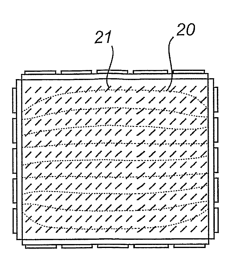
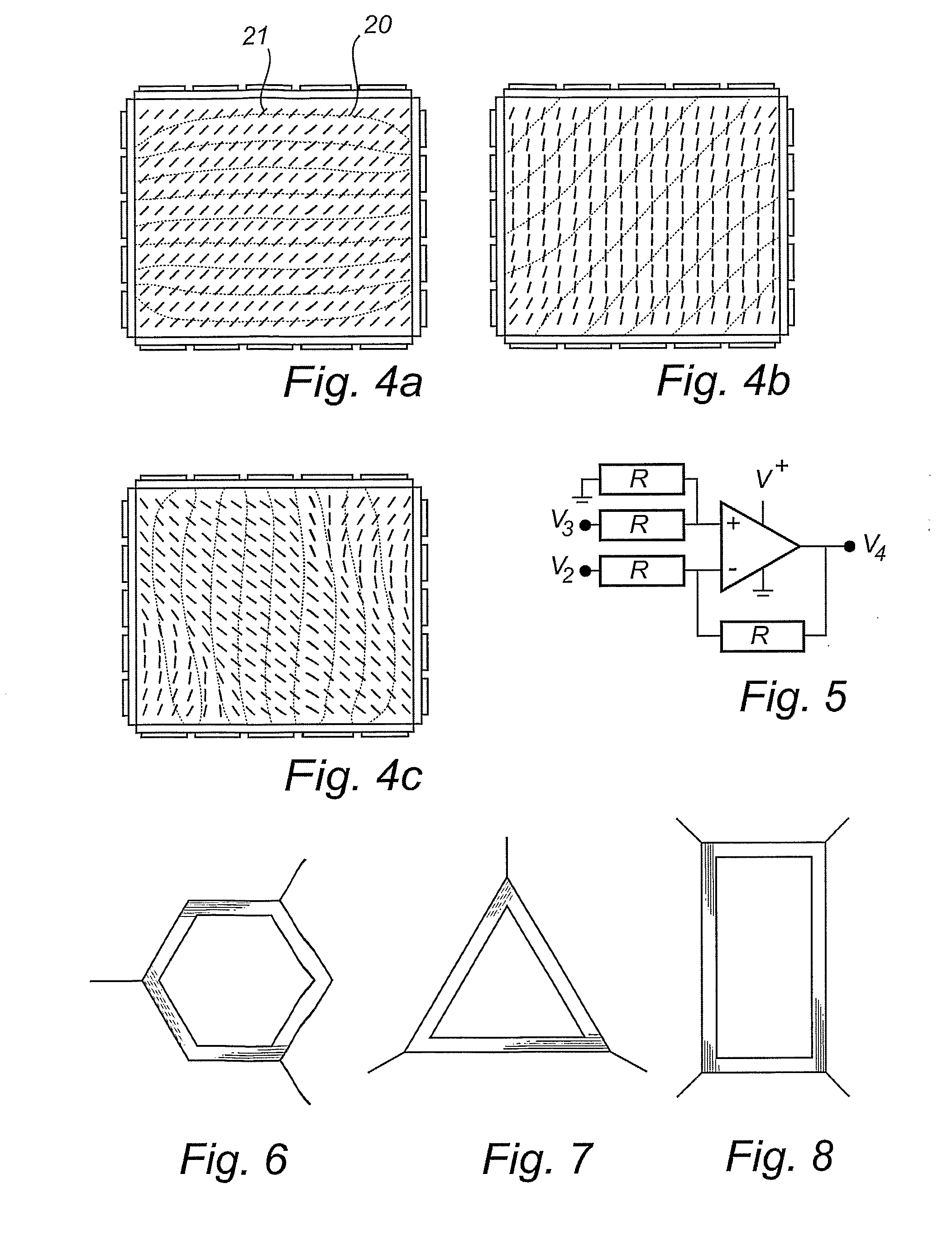
[0006] This allows the electric field to exert a strong torque on the liquid crystal molecules during the switching process, which makes the switching process fast. The resistive paths allow, unlike the conductive electrodes in the prior art, a potential drop along their lengths. Therefore, the resistive path disturbs an electric field much less than a conductive electrode would do, provided that it is not perpendicular to the electric field. This leads to a more uniform electric field, and consequently a more uniform polarization of the liquid crystal material over the pixel area. The more uniform polarization provides improved contrast and brightness properties for the pixel and thus for the display.
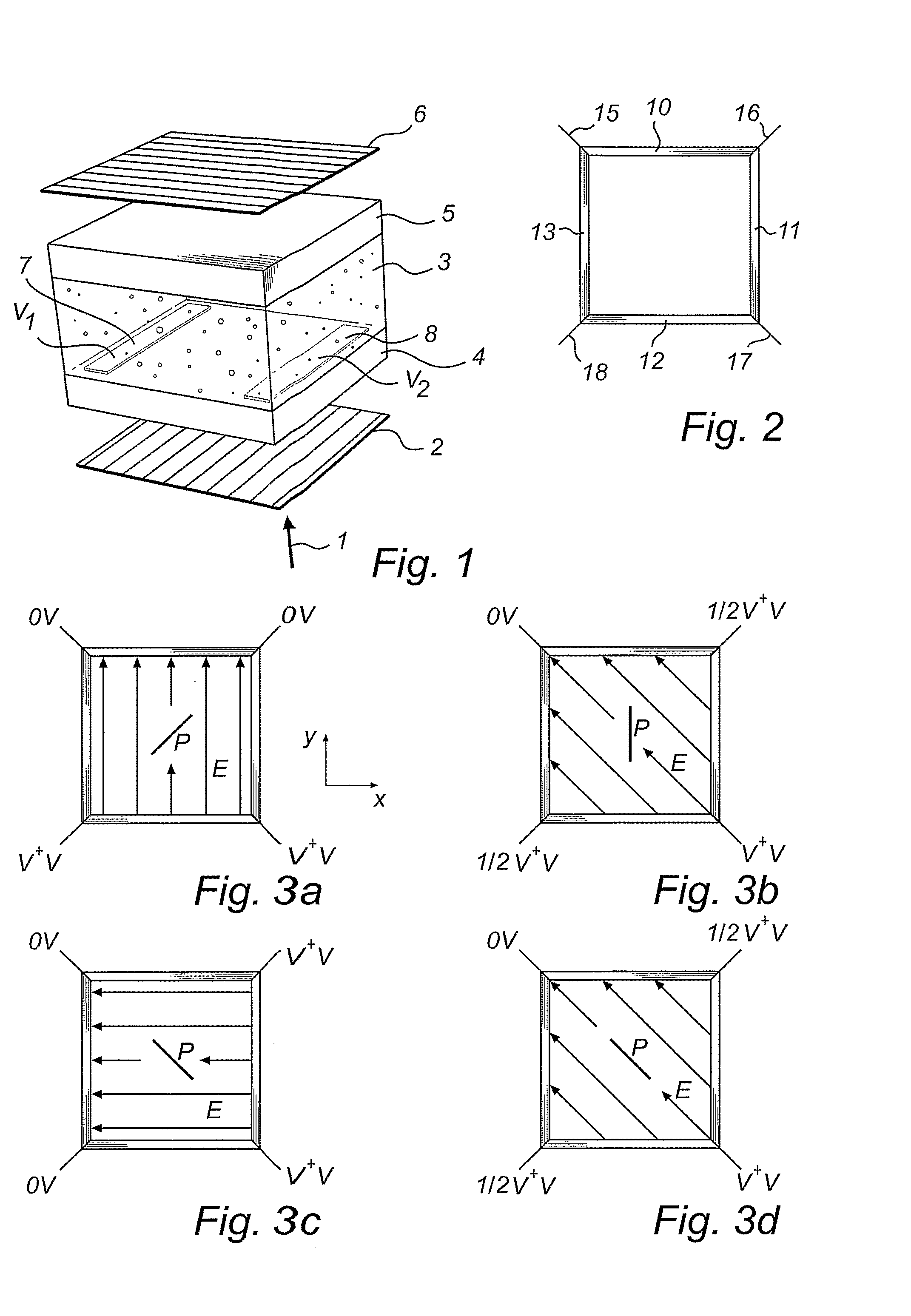
[0010] In a preferred embodiment the display device with rectangular pixels comprises driving means, adapted to feed a first voltage in relation to earth to a connection terminal at a first corner, a second voltage to a connection terminal at a second corner, which is antipodal to the first corner, and to feed voltages between said first and second voltage to the contact terminals at the intermediate third and fourth corners. This allows the generation of a field that is oblique in relation to the pixel geometry and that still is homogenous.
[0011] In a preferred embodiment, the display device comprises an orientation layer, allowing the liquid crystal molecules of the liquid crystal material to rotate freely as long as the molecules extend substantially in a plane that is parallel to said first and second substrates. A display device with such electric field generating means and such an orientation layer may be bi-stable, i.e. the molecules of the liquid crystal material may remain optionally in more than one state, without any applied field.

Problems solved by technology

However, such a display device may be impaired by contrast and brightness disturbances, particularly in the corners of a pixel.

Method used


Image

  • Liquid Crystal Display Device
  • Liquid Crystal Display Device
  • Liquid Crystal Display Device

Examples


Embodiment Construction

[0019] Liquid crystal displays (LCDs) may be used as television screens, personal computer monitors, mobile phone displays etc. An LCD comprises a large number of individually controllable picture elements, hereinafter called pixels, arranged in an array. By controlling the light flow through each pixel, the LCD display may provide an image that may be viewed by a user

[0020]FIG. 1 illustrates schematically the working principle of a pixel in a conventional IPS liquid crystal display.

[0021] In the off-state, incoming light 1 passes through a first polarizer 2 having a first polarizing direction and becomes polarized accordingly. The polarized light then passes through a liquid crystal material 3 contained between a first and a second transparent glass substrate 4, 5. In the dark off-state, the polarizing direction of the liquid crystal material 3 is such, that the polarizing direction of the light passing therethrough remains unchanged. Therefore, the light is then blocked by a sec...


PUM


Abstract

The present invention relates to an in-plane switching liquid crystal display device. In order to enhance the switching characteristics of the display and to improve contrast in displayed images, each pixel area on a substrate in the display is surrounded by strips of resistive material. By applying driving signals to at least three connection terminals, connected to the resistive material strips at different locations, an electric field may be obtained that is homogenous over the pixel area and that may be changed dynamically during the switching process in order to exert maximum torque on liquid crystal molecules in the pixel throughout the switching process.

Description

FIELD OF THE INVENTION [0001] The present invention relates to a liquid crystal display device, comprising a liquid crystal material, disposed between first and second substrates, a plurality of individually controllable picture elements, each picture element comprising electric field generating means for generating electric fields in more than one direction in order to influence the liquid crystal material in the picture element. BACKGROUND OF THE INVENTION [0002] Such a device, using two straight and one L-shaped electrode, is disclosed in WO, 03 / 012537, A1. This configuration may be used to increase the rotational speed of the liquid crystal molecules in a pixel, and therefore to increase the switching speed of the LCD-display, since in average a greater torque may be provided to each liquid crystal molecule during the switching procedure. However, such a display device may be impaired by contrast and brightness disturbances, particularly in the corners of a pixel. SUMMARY OF THE...

Claims


Application Information

Patent Timeline
IPC IPC(8): G09G3/36G02F1/1343
CPCG02F2201/122G02F1/134363G02F1/1343
Inventor MOS, BARRY
Owner KONINKLIJKE PHILIPS ELECTRONICS NV
Learn More