Electromagnetic switch with fixed magnetic core having disc portion formed of stack of base and balance metal sheets
a technology of fixed magnetic core and disc portion, which is applied in the field of electromagnetically-controlled switches, can solve the problems of difficult optimization of the cross-sectional area of the disc portion, and achieve the effect of reducing the manufacturing cos
- Summary
- Abstract
- Description
- Claims
- Application Information
AI Technical Summary
Benefits of technology
Problems solved by technology
Method used
Image
Examples
first embodiment
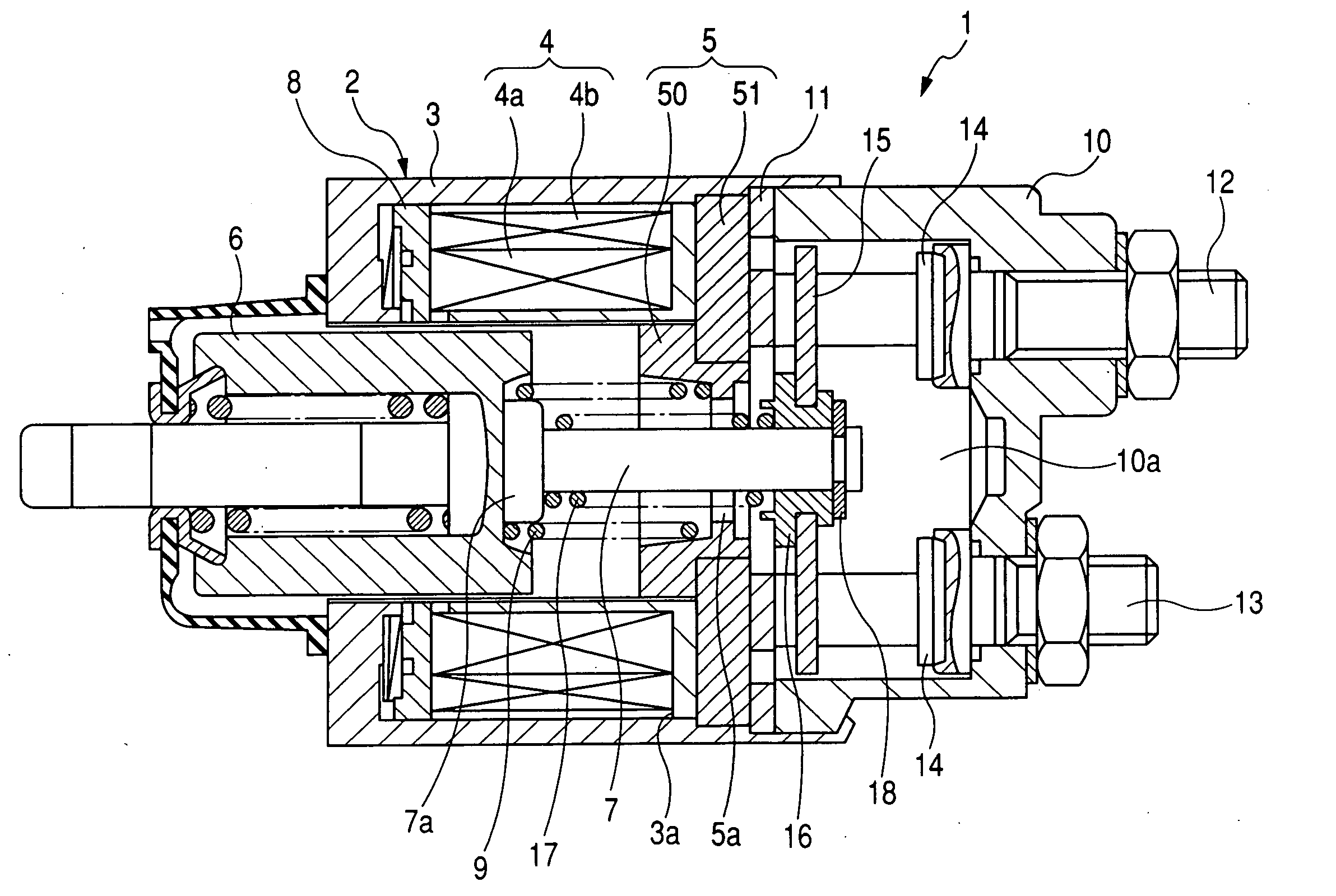
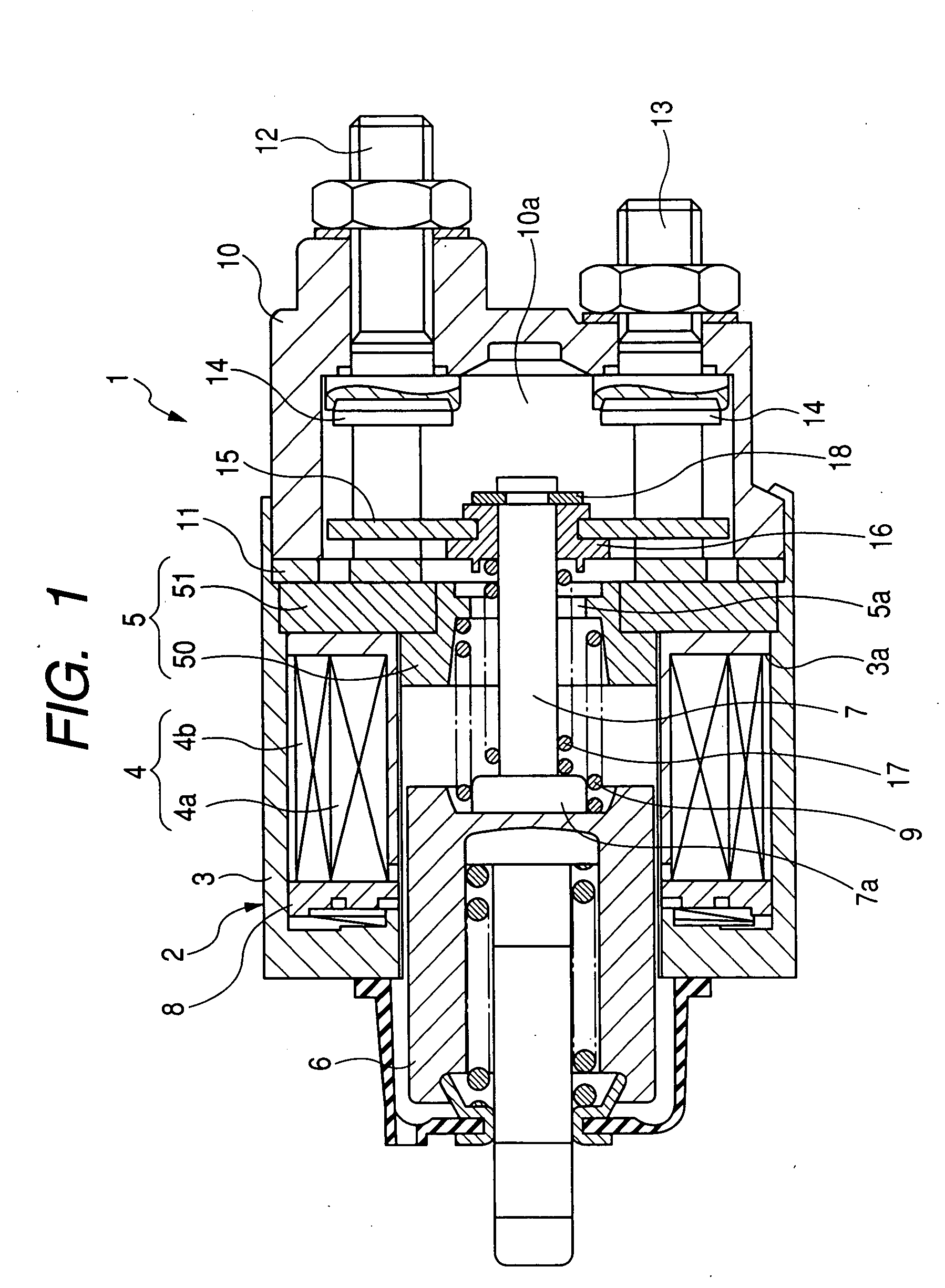
[0035]FIG. 1 shows the overall configuration of an electromagnetic switch 1 according to the first embodiment of the invention. The electromagnetic switch 1 is designed to close and open, for example, a power supply circuit of an automotive starter motor.
[0036]As shown in FIG. 1, the electromagnetic switch 1 includes a pair of fixed contacts 14 spaced away from each other, which make up the main contacts of the power supply circuit of the starter motor, a movable contact 15 working to connect and disconnect the fixed contacts 14, and a solenoid 2 working to actuate the movable contact 15 to make contact with and get away from the fixed contacts 14.
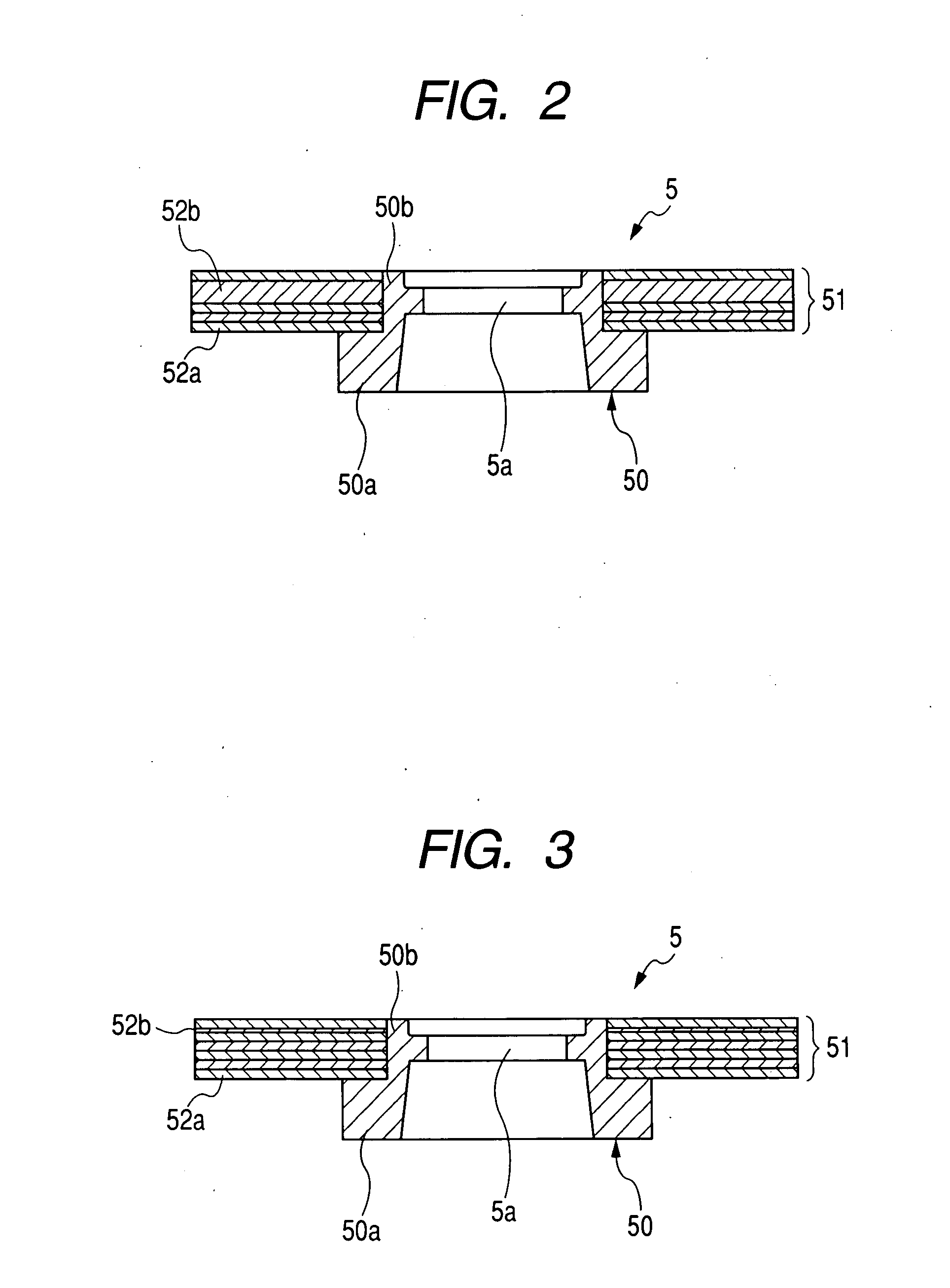
[0037]The solenoid 2 includes a cup-shaped yoke 3, a magnetic coil 4 accommodated in the yoke 3, a fixed magnetic core 5 configured to be magnetized upon energizing the magnetic coil 4, a plunger (i.e., a movable magnetic core) 6 slidably inserted in the magnetic coil 4, and a shaft 7 working to transmit motion of the plunger 6 to the mova...
second embodiment
[0065]FIG. 4 shows a fixed magnetic core 5 according to the second embodiment of the invention.
[0066]As shown in FIG. 4, in this embodiment, the thickness of the balance metal sheet 52b is greater than the thickness of the base metal sheets 52a. Further, the balance metal sheet 52b has been press-fitted onto the boss 50b of the base portion 50 at the last among the metal sheets 20. Consequently, after assembly of the electromagnetic switch 1, the balance metal sheet 52b is farthest from the plunger 6 among the metal sheets 52.
[0067]As described previously, when forming the disc portion 51 by staking the metal sheets 52, the press-fit load for each of the metal sheets 52 is smaller than in the case of a disc portion that is formed of a piece of thick metal sheet. Accordingly, each of the metal sheets 52 may be detached from the boss 50b of the base portion 50 with a smaller force. Consequently, when the plunger 6 collides against the fixed magnetic core 5 during operation of the swit...
third embodiment
[0069]Referring to FIG. 5, in this embodiment, the thickness of the balance metal sheet 52b is less than the thickness of the base metal sheets 52a. Further, the balance metal sheet 52b has been press-fitted onto the boss 50b of the base portion 50 at the first among the metal sheets 52. Consequently, after assembly of the electromagnetic switch 1, the balance metal sheet 52b abuts the inner shoulder 3a of the yoke 3.
[0070]In general, during formation of a metal sheet by pressing, shear drop may occur at edges of the metal sheet. Further, the degree of shear drop decreases with the thickness of the metal sheet.
[0071]Accordingly, in the present embodiment, the balance metal sheet 52b, which has the less thickness than the base metal sheets 52a, has been formed with a smaller degree of shear drop. Consequently, it is possible to secure a sufficiently large contact area A between the balance metal sheet 52b and the inner shoulder 3a, thereby minimizing the magneto-resistance of the mag...
PUM
 Abstract
Description
Claims
Application Information
 - R&D
- Intellectual Property
- Life Sciences
- Materials
- Tech Scout
- Unparalleled Data Quality
- Higher Quality Content
- 60% Fewer Hallucinations
Browse by: Latest US Patents, China's latest patents, Technical Efficacy Thesaurus, Application Domain, Technology Topic, Popular Technical Reports.
© 2025 PatSnap. All rights reserved.Legal|Privacy policy|Modern Slavery Act Transparency Statement|Sitemap|About US| Contact US: help@patsnap.com


