Light emitting element, light emitting device, and electronic device
a technology of light emitting devices and light emitting elements, which is applied in the direction of electric lighting sources, solid-state devices, and light sources. it can solve the problems of difficult to obtain this feature, inorganic el elements consume much power, and are difficult to be used for small-to-medium-sized displays. achieve the effect of improving luminance, reducing power consumption, and improving light output efficiency
- Summary
- Abstract
- Description
- Claims
- Application Information
AI Technical Summary
Benefits of technology
Problems solved by technology
Method used
Image
Examples
embodiment mode 1
[0038] In this embodiment mode, a light emitting material used for a light emitting element of the present invention and a formation method thereof will be described. As light emitting materials used in the present invention, a base material and a material constituted by at least one or more kinds of impurity elements to be a luminescent center can be given. It is to be noted that the impurity elements do not include an element that constitutes the base material.
[0039] As the base material used for the light emitting material, a sulfide, an oxide, or a nitride can be used. In other words, a compound containing an element of Group 2 and an element of Group 16 of the periodic table, or a compound containing an element of Group 12 and an element of Group 16 can be used. Furthermore, a compound containing an element of Group 3 and an element of Group 16, or a compound containing an element of Group 13 and an element of Group 16 can be used. Furthermore, a compound containing an element...
embodiment mode 2
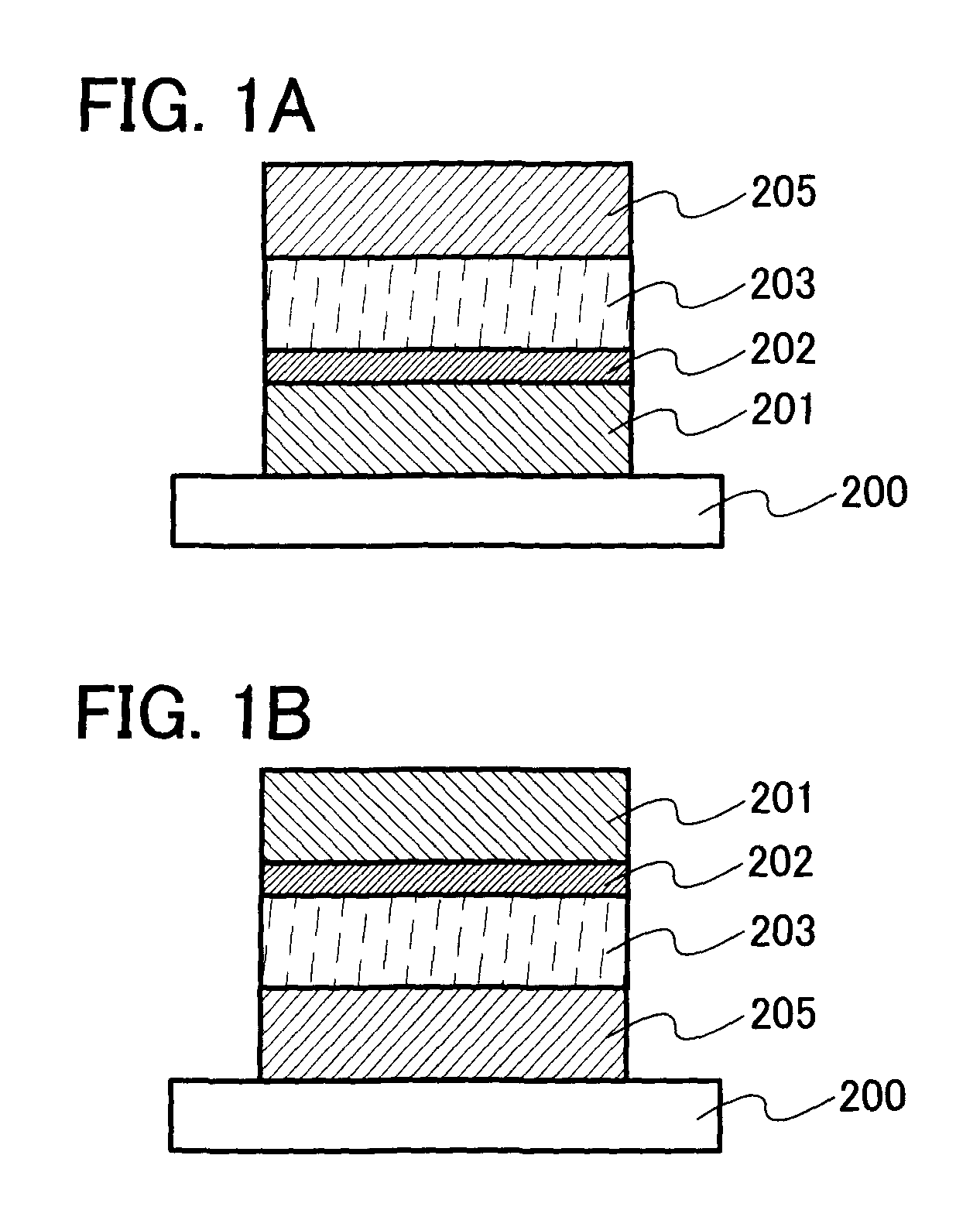
[0055] In this embodiment mode, one mode of a light emitting element of the present invention will be described with reference to FIGS. 1A and 1B. In the present specification, an EL layer refers to a layer provided between a first electrode and a second electrode.
[0056] The light emitting element described in this embodiment mode has, over a substrate 200, a first electrode 201, a second electrode 205, a light emitting layer 203, and a barrier layer 202. The light emitting element described in this embodiment mode emits light by voltage application between the first electrode 201 and the second electrode 205. In this embodiment mode, a case where light emission is obtained when a potential of the second electrode is made higher than a potential of the first electrode will be described.
[0057] The substrate 200 is used as a support of the light emitting element. For the substrate 200, glass, plastic, or the like can be used, for example. It is to be noted that another material may ...
embodiment mode 3
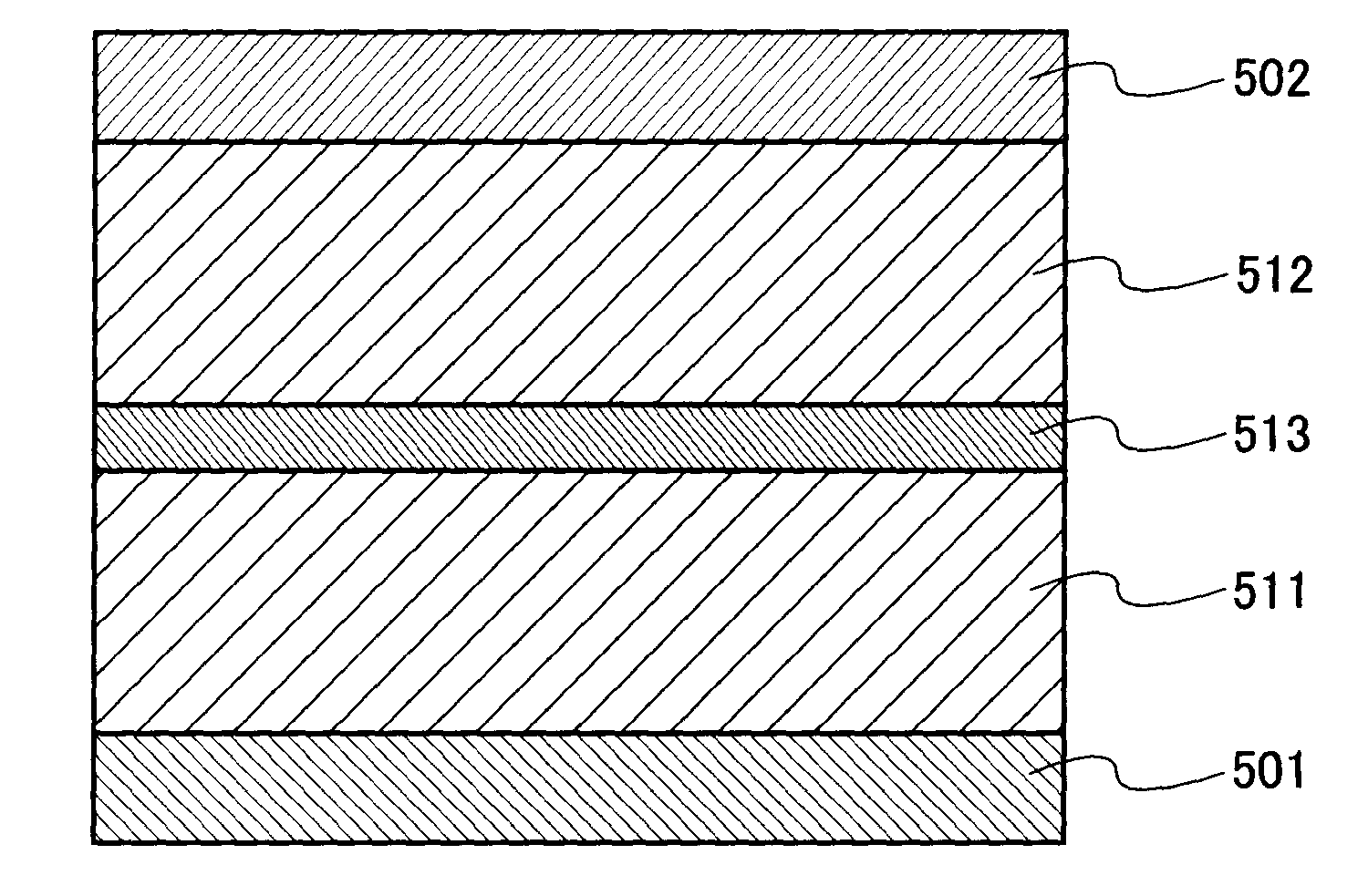
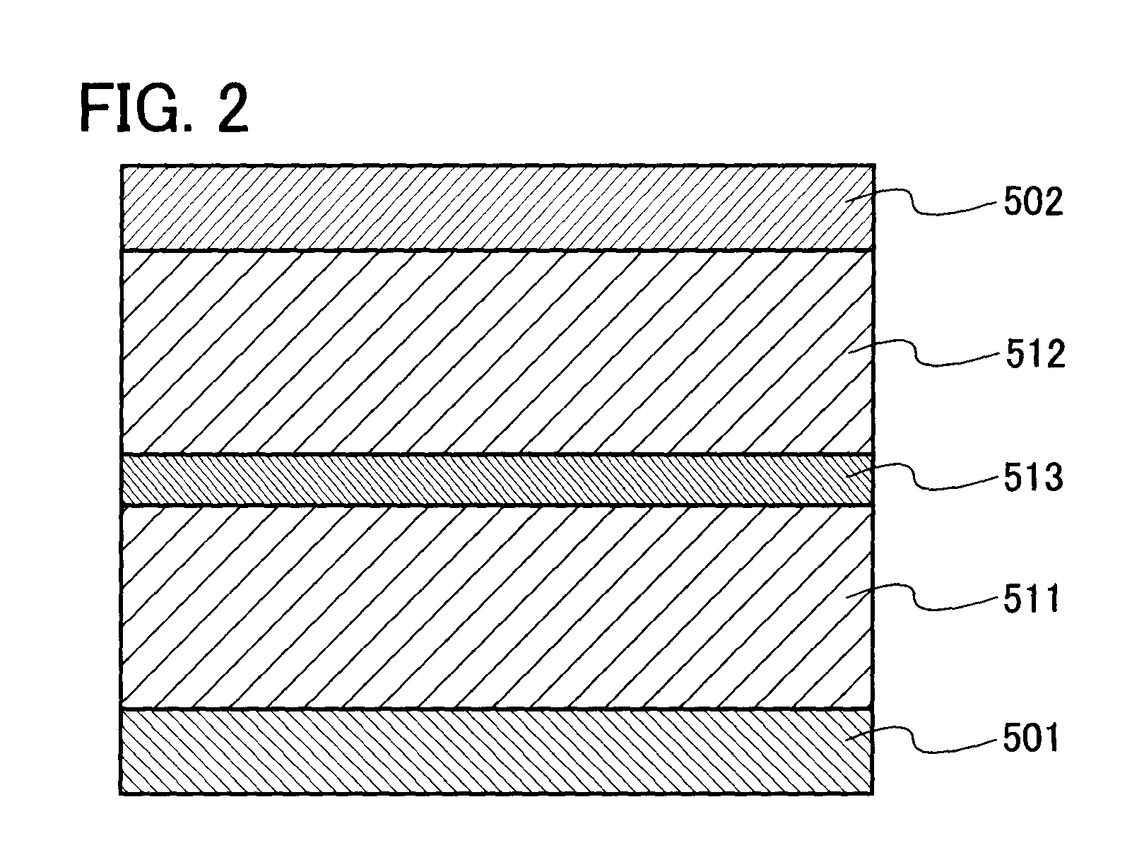
[0070] In this embodiment mode, a mode of a light emitting element with a structure in which a plurality of light emitting units of the present invention are stacked (hereinafter referred to as a stacked element) will be described with reference to FIG. 2. This light emitting element has a plurality of light emitting units between a first electrode and a second electrode.
[0071] In FIG. 2, a first light emitting unit 511 and a second light emitting unit 512 are stacked between a first electrode 501 and a second electrode 502. Materials similar to those in Embodiment Mode 2 can be applied to the first electrode 501 and the second electrode 502. Furthermore, the first light emitting unit 511 and the second light emitting unit 512 have the same structure, which is similar to the structure described in Embodiment Mode 2. In other words, a structure in which a barrier layer, a light emitting layer, and a layer containing a composite material are stacked similarly to Embodiment Mode 2 can...
PUM
 Abstract
Description
Claims
Application Information
 - R&D
- Intellectual Property
- Life Sciences
- Materials
- Tech Scout
- Unparalleled Data Quality
- Higher Quality Content
- 60% Fewer Hallucinations
Browse by: Latest US Patents, China's latest patents, Technical Efficacy Thesaurus, Application Domain, Technology Topic, Popular Technical Reports.
© 2025 PatSnap. All rights reserved.Legal|Privacy policy|Modern Slavery Act Transparency Statement|Sitemap|About US| Contact US: help@patsnap.com


