
Muntin Clip

a technology of sash window assembly and mutine grid, which is applied in the direction of building components, constructions, building constructions, etc., can solve the problems of clip manufacturers, window manufacturers or assemblers to incur costs associated with maintaining and otherwise dealing with large and varied inventories, and the burden on clip manufacturers and window assemblers with large clip inventories, etc., to achieve the effect of strengthening connection

Inactive Publication Date: 2007-08-23
NEWELL OPERATING COMPANY
View PDF60 Cites 8 Cited by
  • Summary
  • Abstract
  • Description
  • Claims
  • Application Information

AI Technical Summary

Benefits of technology

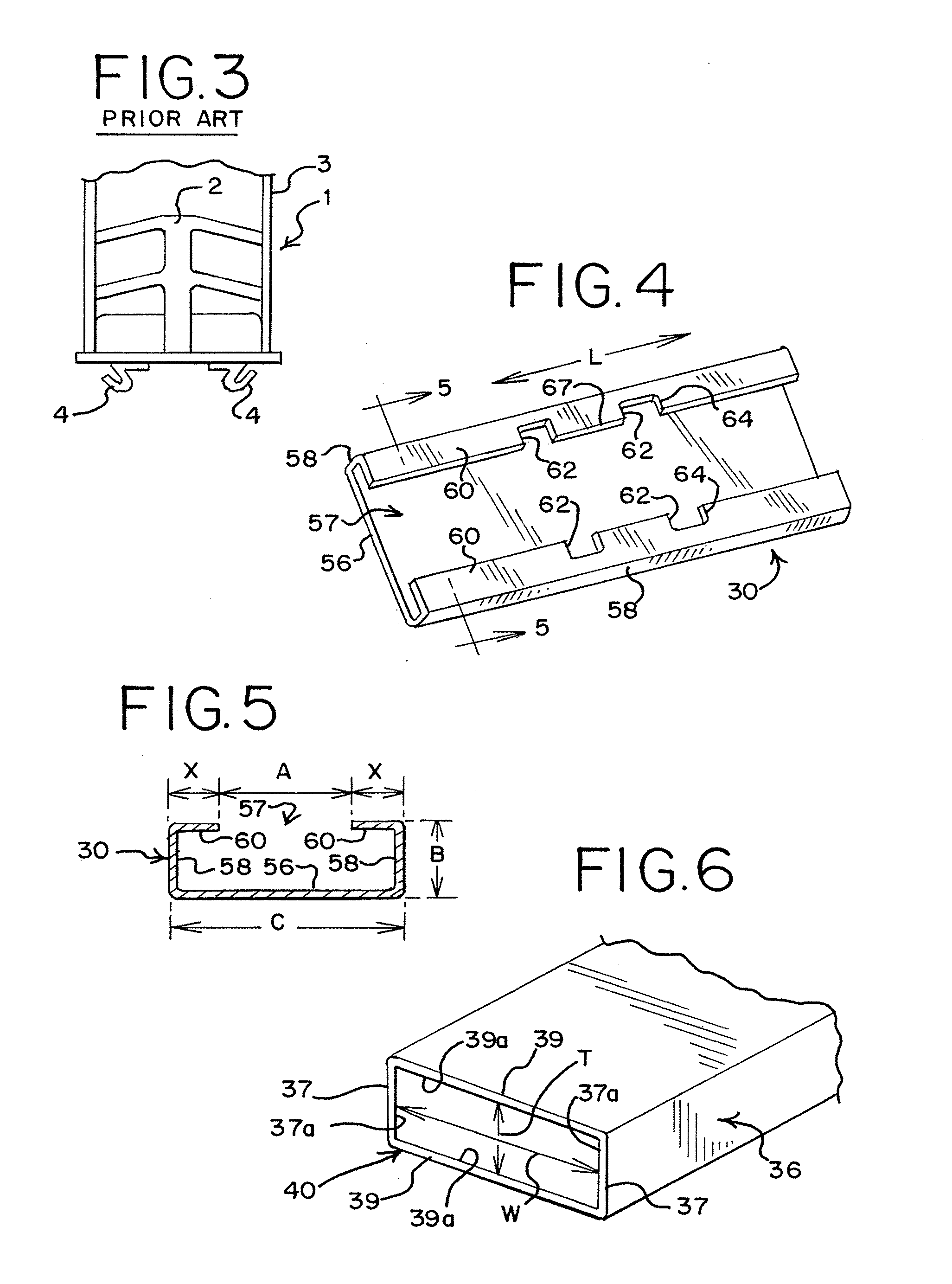
[0014] According to another aspect of the invention, a flexible hinge member connects the first segment of the bar support to the second segment of the bar support, allowing the muntin clip assembly to move between an unfolded position and a folded position.
[0015] According to another aspect of the invention, a tension mechanism exerts outward force on the first and second segments of the base member when the muntin clip assembly is in the folded position, allowing for enhanced connection to a spacer frame and also for connection to a variety of different spacer frames.

Problems solved by technology

One drawback resulting from this fact is that muntin clip manufactures must design and produce a separate clip to match each potential size / shape of muntin bar available on the market and to also match with a variety of sizes of spacer frames.
This costs clip manufacturers, and window manufacturers or assemblers to incur costs associated with maintaining and otherwise dealing with large and varied inventories of muntin clips.
This in turn causes clip manufacturers and window assemblers to be burdened with large clip inventories.
In addition, certain muntin clip designs require complex molds in the manufacturing process.

Method used


Image

  • Muntin Clip
  • Muntin Clip
  • Muntin Clip

Examples


Embodiment Construction

[0036] While this invention is susceptible of embodiment in many different forms, there are shown in the drawings and will herein be described in detail preferred embodiments of the invention with the understanding that the present disclosure is to be considered as an exemplification of the principles of the invention and is not intended to limit the broad aspect of the invention to the embodiments illustrated.

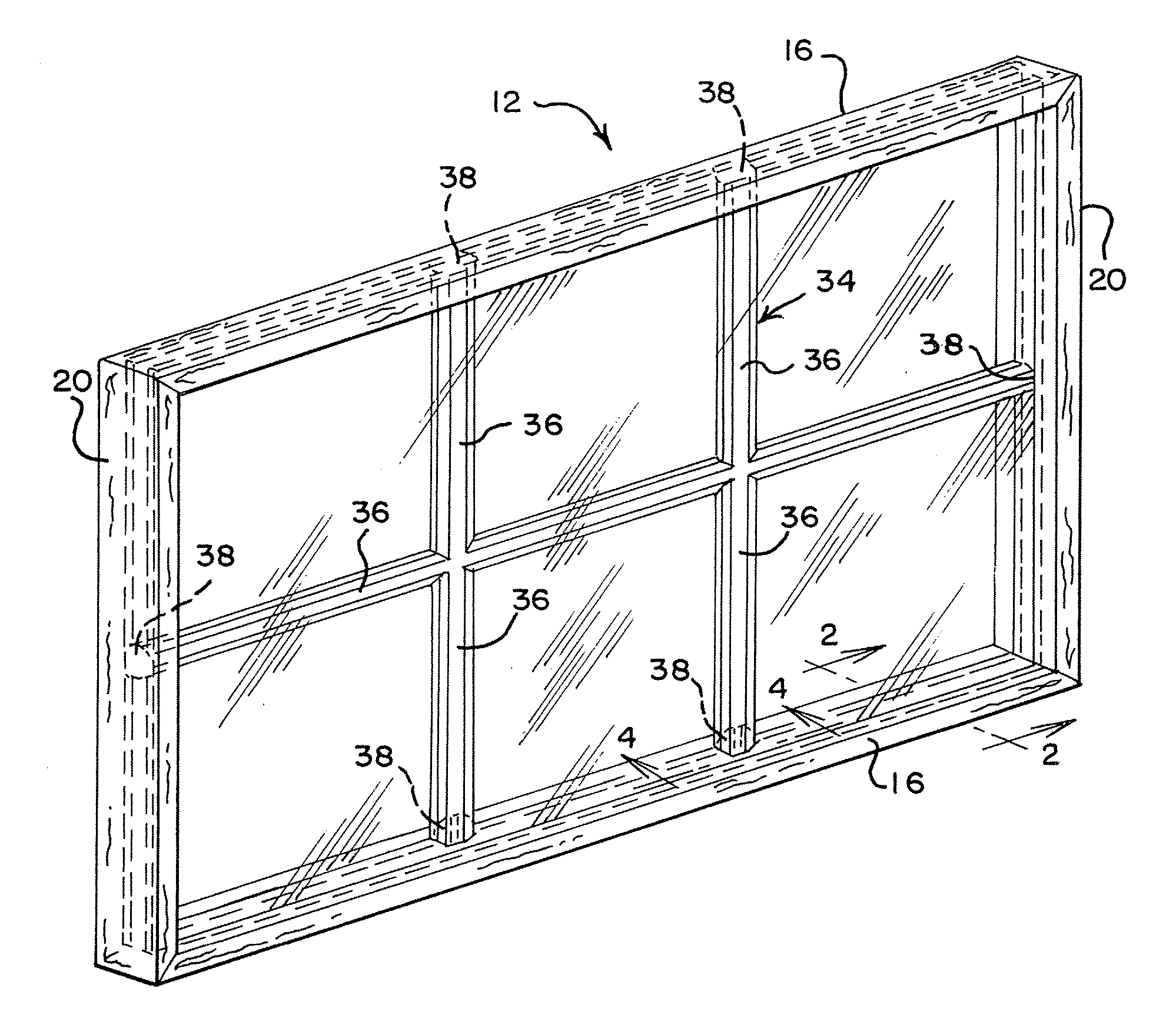
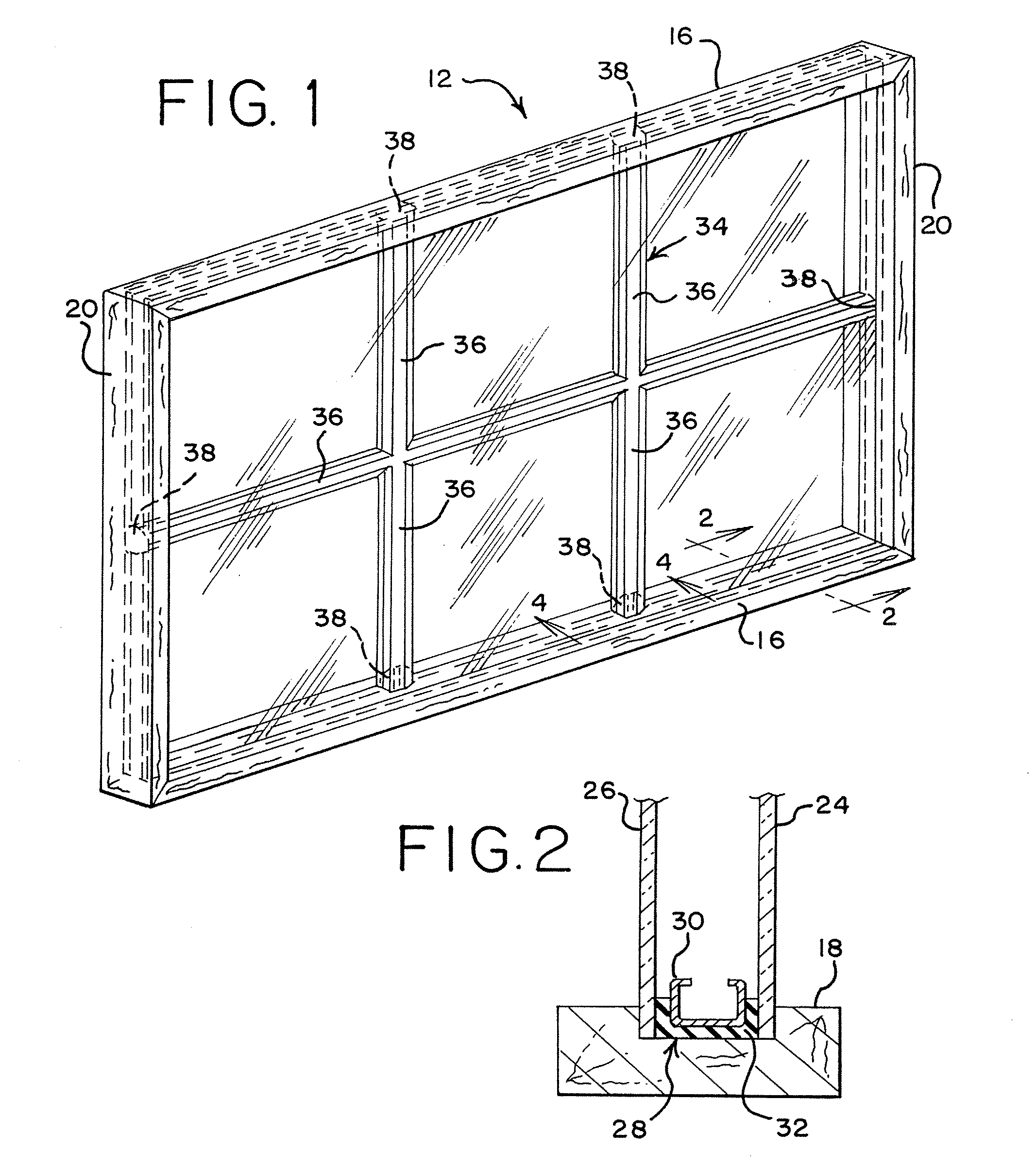
[0037] FIG.1 shows a sash window 12 comprised of a top sash rail 16, a base sash rail 18 and a pair of vertical stiles 20. Although not shown, the sash window 12 may be mounted, slidingly or otherwise, within a master frame, such as, in a single or double hung window arrangement as is well known in the art. It is also understood that other hardware can be incorporated into the sash window 12 as is known in the art.

[0038] As shown in FIG. 2, each sash window 12 also includes a first pane of glass 24 and a second pane of glass 26 mounted in parallel relationship to one another...


PUM


Abstract

A muntin clip is adapted to be connected to a muntin bar end and a spacer frame. The muntin clip includes a base member adapted for connection to the spacer frame and a bar support adapted for connection to the muntin bar end. The base member has a first segment, a second segment, and a mount structure. The bar support extends from the base member and has a first segment extending from the first segment of the base member and a second segment extending from the second segment of the base member. A flexible hinge member connects the first segment of the bar support to the second segment of the bar support, allowing the muntin clip assembly to move between an unfolded position and a folded position. A tension mechanism exerts outward force on the first and second segments of the base member when the muntin clip assembly is in the folded position.

Description

CROSS-REFERENCE TO RELATED APPLICATIONS [0001] This application claims the benefit of U.S. Provisional Patent Application No. 60 / 757,116, filed Jan. 6, 2006, which is expressly incorporated herein by reference and made a part hereof.TECHNICAL FIELD [0002] This invention relates generally to muntin grids for sash window assemblies and more specifically to a muntin clip for positioning the grid within a sash window. BACKGROUND OF THE INVENTION [0003] Double hung window assemblies typically include a pair of sash windows slidably mounted within a master frame. In the past, sash windows were provided with a grid of muntin bars, typically made of wood, that separated and held multiple panes of glass within a sash. Each pane would be mounted within the sash in the same plane. Now, double or multiple pane windows are provided, otherwise known as insulated or thermo-pane window assemblies. These insulated window assemblies include a pair of glass panes mounted in parallel relation to one an...

Claims


Application Information

Patent Timeline
IPC IPC(8): E04C2/38
CPCE06B3/6675E06B3/667
Inventor GARAY, ANTONIO A.
Owner NEWELL OPERATING COMPANY
Learn More