
Paddle, developing device and image forming apparatus

a development device and paddle technology, applied in the field of paddles, can solve the problems of high die cost, high machining cost, and difficulty in obtaining such an elongated paddle with a high degree of accuracy,

Inactive Publication Date: 2007-08-16
MURATA MASCH LTD
View PDF2 Cites 0 Cited by
  • Summary
  • Abstract
  • Description
  • Claims
  • Application Information

AI Technical Summary

Benefits of technology

[0008]In order to overcome the problems described above, preferred embodiments of the present invention prevent an occurrence of the defective image formation due to spaces generated between the blades of the plurality of components divided in the axial direction of the elongated paddle.
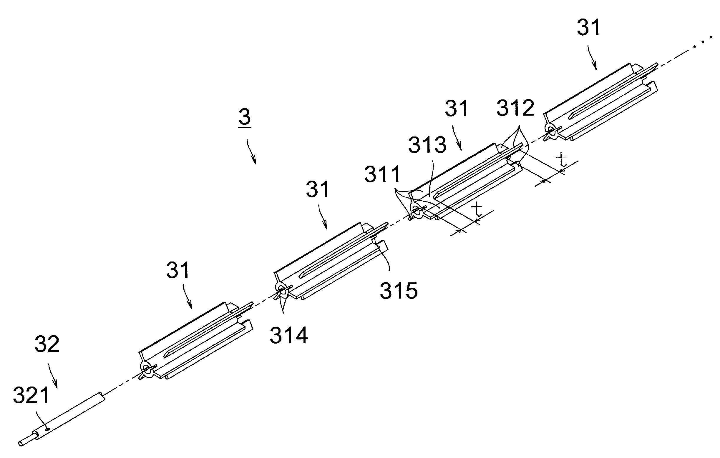
[0010]According to the image forming apparatus of the present preferred embodiment, since the paddle supply member for supplying the developer to the developer device while agitating the same is formed by connecting the axially divided plurality of components, and the component includes blades extending in the axial direction, spaces are generated in the axial direction between the blades of the connected components. However, since the blades provided on the component are overlapped in the circumferential direction with the blades provided on the components adjacent to the corresponding component, the spaces generated between the blades of the connected components are shifted from each other in the axial direction. Therefore, the paddle supply member can agitate and desirably supply the developer along the entire axial direction by the rotation of the paddle supply member since at least one of the blades exists in the circumferential direction, so that generation of the defective image formation can be prevented.
[0012]According to the image forming apparatus of this preferred embodiment, since the components include the blades extending in the radial direction, and the blades of the component adjacent in the circumferential direction are axially shifted in position, the paddle supply member can agitate and further desirably supply the developer, and occurrence of the defective image formation can further be prevented.
[0014]According to the image forming apparatus in this preferred embodiment, since the blades provided on the component and the blades provided on the components adjacent to the corresponding component are formed continuously, an elongated paddle supply member can be provided having long blades continuing in the axial direction to agitate and supply the developer, so that the occurrence of the defective image formation can further be prevented.
[0016]According to the image forming apparatus of this preferred embodiment, since the respective components have the same shape, connection is achieved without considering the connecting order of the components, so that the manufacturing process of the paddle supply member can be simplified. In addition, since there is only one type of the component, the controlling process of the paddle supply member can be simplified.

Problems solved by technology

It is difficult to obtain such an elongated paddle with a high degree of accuracy by metal machining, and the machining cost is expensive.
Injection molding of the elongated paddle with resin or plastic requires a high die cost, and it is also difficult to eliminate molding distortion generated in the axial (longitudinal) direction.
Such spaces s degrade the accuracy of supplying the toner by the paddle, and cause defective image formation.
For example, since the developer is not agitated at positions where the spaces s exist, the developer conglomerates and causes defective image formation.
In such a case, there is a problem such that the developer is not supplied to a portion of the surface of the photoreceptor drum which opposes the developing sleeve.
Hence, the toner is not adhered to the corresponding portion and hence an image with a void is formed on the printing paper, so that defective image formation results.
Since there are the spaces s between the blades 902 of the paddle 900, if there are portions where a sufficient required amount of the developer is not held on the surface of the developing sleeve, there may be a case in which an image having a density less than that of the desired level is formed on the printing paper, so that defective image formation results.

Method used


Image

  • Paddle, developing device and image forming apparatus
  • Paddle, developing device and image forming apparatus
  • Paddle, developing device and image forming apparatus

Examples


Embodiment Construction

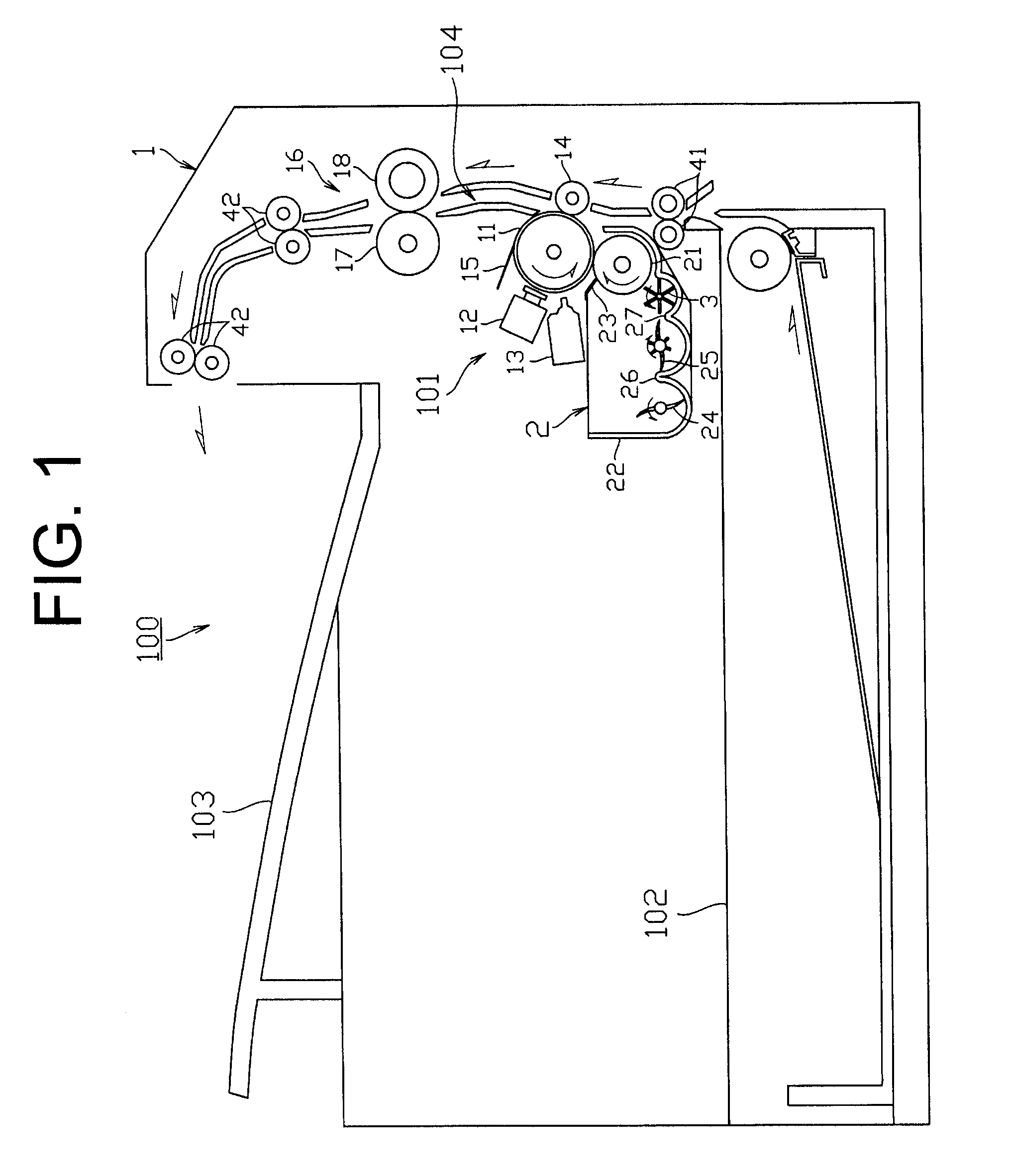
[0030]As shown in FIG. 1, a copy / facsimile multi-function machine 100 provided with an image forming apparatus according to a preferred embodiment of the present invention includes a machine body 1, and a developing unit (developing section) 2 mounted to the machine body 1 which defines a portion of the image forming apparatus. The developing unit 2 includes a paddle (paddle supply member) 3 that agitates and supplies developer therein.

[0031]An image forming unit including the developing unit 2 is disposed in the machine body 1. In addition, the machine body 1 is provided with a paper feed cassette 102 which supplies printing paper in sequence on a bottom portion thereof, and a paper discharge tray 103 above the image forming unit 101, respectively. Although not shown, the copy / facsimile multi-function machine 100 includes an image reading unit that functions as a flat-bed scanner and an operating panel for inputting instructions to read the image, start the printing job, and so on,...


PUM


Abstract

A paddle includes a plurality of axially divided components that are connected together, each component including axially extending blades, wherein the blades overlap with blades provided on a component adjacent to the corresponding component in the circumferential direction.

Description

BACKGROUND OF THE INVENTION[0001]1. Field of the Invention[0002]The present invention relates to an image forming apparatus for use in, for example, a copying machine, a printer, a facsimile and so on. More specifically, the present invention relates to an image forming apparatus provided with a developing device, wherein the developing device has a paddle and the paddle supplies developer while agitating the same.[0003]2. Description of the Related Art[0004]An image forming apparatus used for a copying machine, a printer, a facsimile, and a multi-function machine which includes at least two of these functions selectively exposes the surface of a uniformly charged photoreceptor drum according to image information to form a latent image, develops the formed electrostatic latent image to form a toner image, and transfers the toner image to printing paper to print an image. Subsequently, the toner image which is not yet fixed is fixed on the printing paper. The developer is stored in a...

Claims


Application Information

Patent Timeline
IPC IPC(8): G03G15/08
CPCG03G2215/0819G03G15/0822
Inventor KAWAI, HIDEAKI
Owner MURATA MASCH LTD
Learn More