Image forming apparatus having nip portion holding recording material between transfer member and image bearing member

a technology of image forming apparatus and transfer member, which is applied in the direction of electrographic process apparatus, instruments, corona discharge, etc., can solve the problems of abnormal discharge, large potential difference, and defective image generation, and achieve the effect of preventing the generation of defective images

Active Publication Date: 2020-03-03
CANON KK
View PDF5 Cites 0 Cited by
  • Summary
  • Abstract
  • Description
  • Claims
  • Application Information

AI Technical Summary

Benefits of technology

[0007]The present disclosure was made for solving at least one of those problems and can provide an image forming apparatus which can prevent a defective image generated because of the unevenness in potential due to the abnormal discharge and a potential difference on the photosensitive member surface.

Problems solved by technology

However, when such a direct transfer method is used and if a transfer bias is applied when a recording material does not exist at a nip portion (transfer contact portion) between the photosensitive member and the transfer member, a large potential difference may occur between the transfer member and the photosensitive member, which causes abnormal discharge.
Thus, a defective image may be generated.
However, when the method disclosed in Japanese Patent Laid-Open No. 10-78712 is used, the following problems may disadvantageously occur.
If the void is formed, a potential difference between the photosensitive member and the transfer member may cause abnormal discharge in the void.
A preparation for image forming has started when such a void is formed, and when a transfer bias for image forming is applied, discontinuous discharge occurs between the photosensitive member and the transfer member at the void, which may cause minute unevenness in potential on the surface of the photosensitive member.
When charging cannot level the minute unevenness in potential, a defective image may be generated.
This abnormal discharge becomes more significant when the transfer bias is high, like a case where a recording material does not exist in the nip portion between the transfer member and the photosensitive member.
On the other hand, because transfer current is not fed from the transfer member to the surface of the photosensitive member, uneven surface potential occurs on the photosensitive member after passing through the transfer nip between the void and the remaining even part.
When charging cannot level the unevenness in potential, a defective image may sometimes be generated.

Method used


Image

  • Image forming apparatus having nip portion holding recording material between transfer member and image bearing member
  • Image forming apparatus having nip portion holding recording material between transfer member and image bearing member
  • Image forming apparatus having nip portion holding recording material between transfer member and image bearing member

Examples


embodiment 1

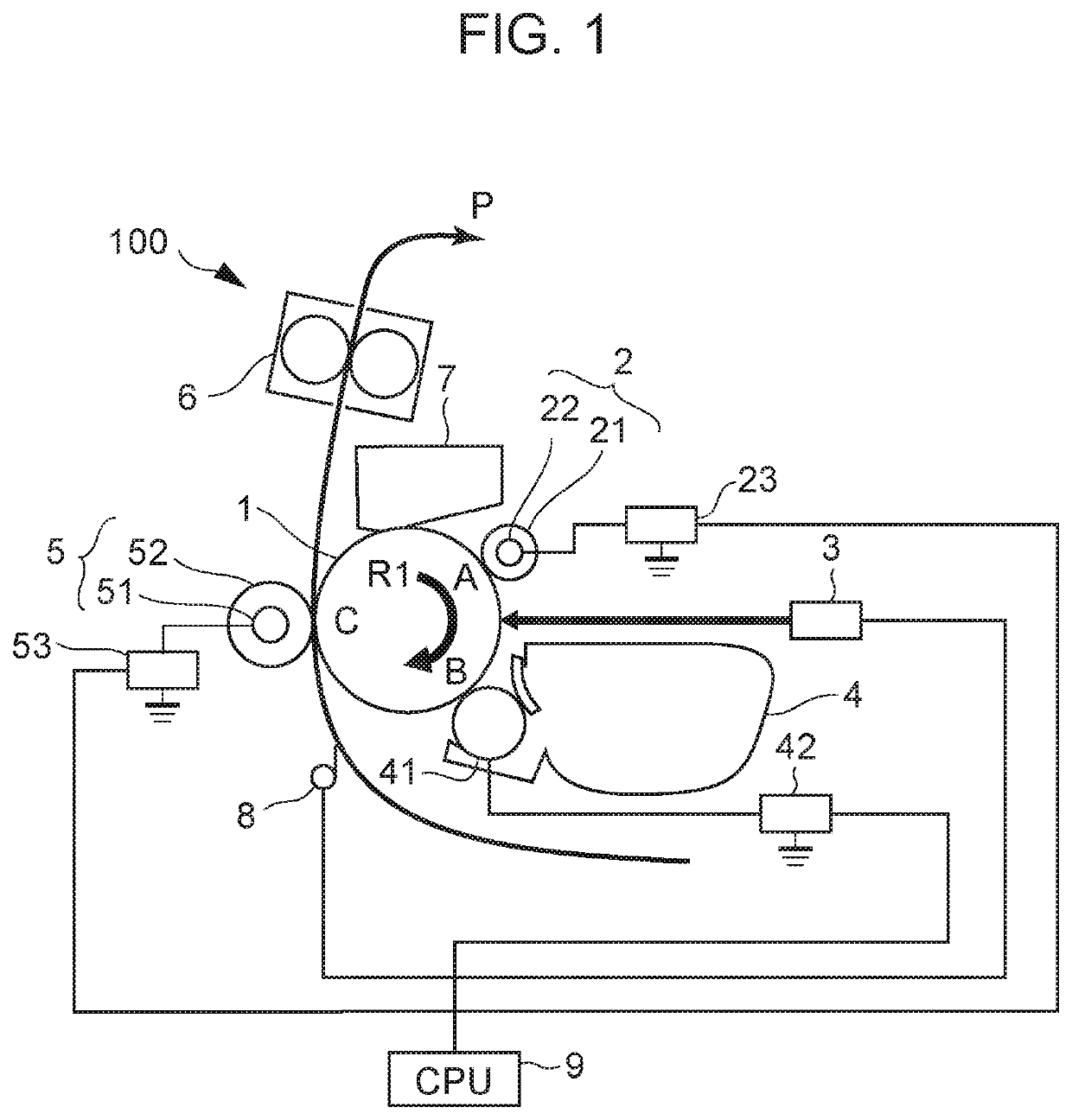
[0019]With reference to FIG. 1, a configuration of an image forming apparatus 100 according to Embodiment 1 will be described, and image forming processing according to Embodiment 1 will be described. FIG. 1 is a schematic cross-sectional view illustrating a configuration of the image forming apparatus 100 according to Embodiment 1.

[0020]As illustrated in FIG. 1, the image forming apparatus 100 according to Embodiment 1 includes a photosensitive drum 1 as a rotatable image bearing member, a charging roller 2 in contact with the photosensitive drum 1 as a charging member, an exposure device 3 as an exposure unit, a developing device 4, and a transfer roller 5 as a transfer unit. The image forming apparatus 100 further includes a fixing device 6, a cleaning device 7, a recording-material detecting member 8 as a recording-material-conveyance detecting unit, and a controller 9 as a central processing unit (CPU) operating as a control unit.

[0021]The photosensitive drum 1 has a diameter Φ...

embodiment 2

[0084]According to Embodiment 1, a monochrome image forming apparatus 100 is used which includes roller-shaped transfer member 5 configured to transfer a toner image on a surface of the photosensitive drum 1 onto paper P. On the other hand the present disclosure is also applicable to a full-color image forming apparatus 101 including a belt-shaped transfer member (transfer belt) 54 as illustrated in FIG. 8.

[0085]The image forming apparatus 101 has process cartridges Cy, Cm, Cc, and Cb storing toners of yellow y, magenta m, cyan c, and black b and detachably attached to the apparatus main body. A part of a printing operation is executed with the process cartridges Cy, Cm, Cc, and Cb attached to the apparatus main body. The transfer member 54 has transfer rollers 5y, 5m, 5c, and 5b provided as conductive pressure adjusting member at positions facing photosensitive drums 1y, 1m, 1c, and 1b of the process cartridges Cy, Cm, Cc, and Cb. Transfer voltage applying units, not illustrated, a...


PUM


Abstract

A nip portion is formed between a transfer member and an image bearing member. During an image transfer operation, a first transfer voltage is applied so that a first charging voltage is applied to the surface of the image bearing member forming the nip portion. Before paper enters, a second transfer voltage is applied so that a third charging voltage is applied to the surface of the image bearing member forming the nip portion. A void is formed by the image bearing member, the transfer member and the paper within the nip portion. Before an image transfer operation and the void is formed, one of the first and second transfer voltages and a third transfer voltage is applied so that a second charging voltage having a same polarity as the first charging voltage and being lower in absolute value is applied to the surface of the image bearing member.

Description

BACKGROUND OF THE INVENTIONField of the Invention[0001]A disclosed aspect of the embodiments relates to an image forming apparatus, such as an electrophotographic printer and an electrophotographic copier, configured to form an image on a recording material.Description of the Related Art[0002]Conventionally, image forming apparatuses such as a copier and a printer may often apply an electrostatic recording method, an electrophotographic recording method, and so on.[0003]As one of such recording methods, a direct transfer method has been known which transfers a toner image formed on a surface of a photosensitive member onto a recording material conveyed to between the photosensitive member and a transfer member in a transfer part based on a potential difference occurring between a photosensitive member and a transfer member.[0004]However, when such a direct transfer method is used and if a transfer bias is applied when a recording material does not exist at a nip portion (transfer co...

Claims


Application Information

Patent Timeline
Patent Type & Authority Patents(United States)
IPC IPC(8): G03G15/02G03G15/16
CPCG03G15/1675G03G15/0266G03G15/1665
Inventor MIZUKOSHI, SHUNSUKEFUKATSU, MAKOTOISOBE, YUTATOKIWA, SHUHEI
Owner CANON KK
Why Eureka
Try Eureka