Capillary tube for holding optical fiber and connecting structure for optical component

Active Publication Date: 2007-08-16
NIPPON ELECTRIC GLASS CO LTD
View PDF2 Cites 4 Cited by
  • Summary
  • Abstract
  • Description
  • Claims
  • Application Information

AI Technical Summary

Benefits of technology

[0012] In light of the aforementioned circumstance, technical objects of the present invention are to achieve the aligning work between the optical component such as the optical waveguide device and the capillary tube by a simple operation, and respond to the request of appropriately mounting the optical waveguide device and the capillary tube on the same flat surface, and significantly decrease a height difference between the optical component and the capillary tube when both are connected, fixed, and mounted on the same flat surface, and thus both can be packaged by the casing without leading to saccadic movement and early deterioration.
[0032] As described above, according to the present invention, when an optical component such as an optical waveguide device is connected and fixed to a capillary tube, these can be mounted on the same flat surface with stability, and moreover these can be relatively easily aligned while, being held with stability, avoiding disadvantageous and inconvenience of handling. In addition, when the optical component and the capillary tube are mounted on the same flat surface while being connected and fixed to each other, a height difference between the top surface of the optical component and the top-surface side end portion of the capillary tube is less likely to occur. Therefore, when these are packaged with the casing, the generation of the gap is prevented and thus the generation of saccadic movements is prevented. In addition, the problems of the generation of the improper stress, which are due to the difference in thermal expansion caused by filling the gap with an adhesive or the like, and the early deterioration due to the generation of the stress are solved.

Problems solved by technology

In addition, due to the presence of the gap, saccadic movements are generated, and moreover even when the gap is filled with an adhesive or a spacer is interposed in order to reduce the saccadic movements, a difference in thermal expansion or the like between the adhesive or the spacer and the optical waveguide device generates an improper stress, thereby leading to early deterioration.
Therefore, even by the structure disclosed in the Patent document 2, the height difference causes a problem such as early deterioration, as in the structure disclosed in the aforementioned Patent document 1.
Moreover, the relative rotational angle of the insertion hole and the core must be precisely adjusted, and furthermore the handling of the insertion hole and the core is inconvenient and thus troublesome and complicated aligning work is required, thereby leading to a problem of significantly decreasing workability or operating efficiency.
In addition, when both are required to be mounted on the same flat surface in terms of layout or the like, there arises a fatal problem that both cannot be firmly mounted with stability.

Method used


Image

  • Capillary tube for holding optical fiber and connecting structure for optical component
  • Capillary tube for holding optical fiber and connecting structure for optical component
  • Capillary tube for holding optical fiber and connecting structure for optical component

Examples


Embodiment Construction

[0043] Hereinafter, embodiment of the present invention will be described with reference to the accompanying drawings.

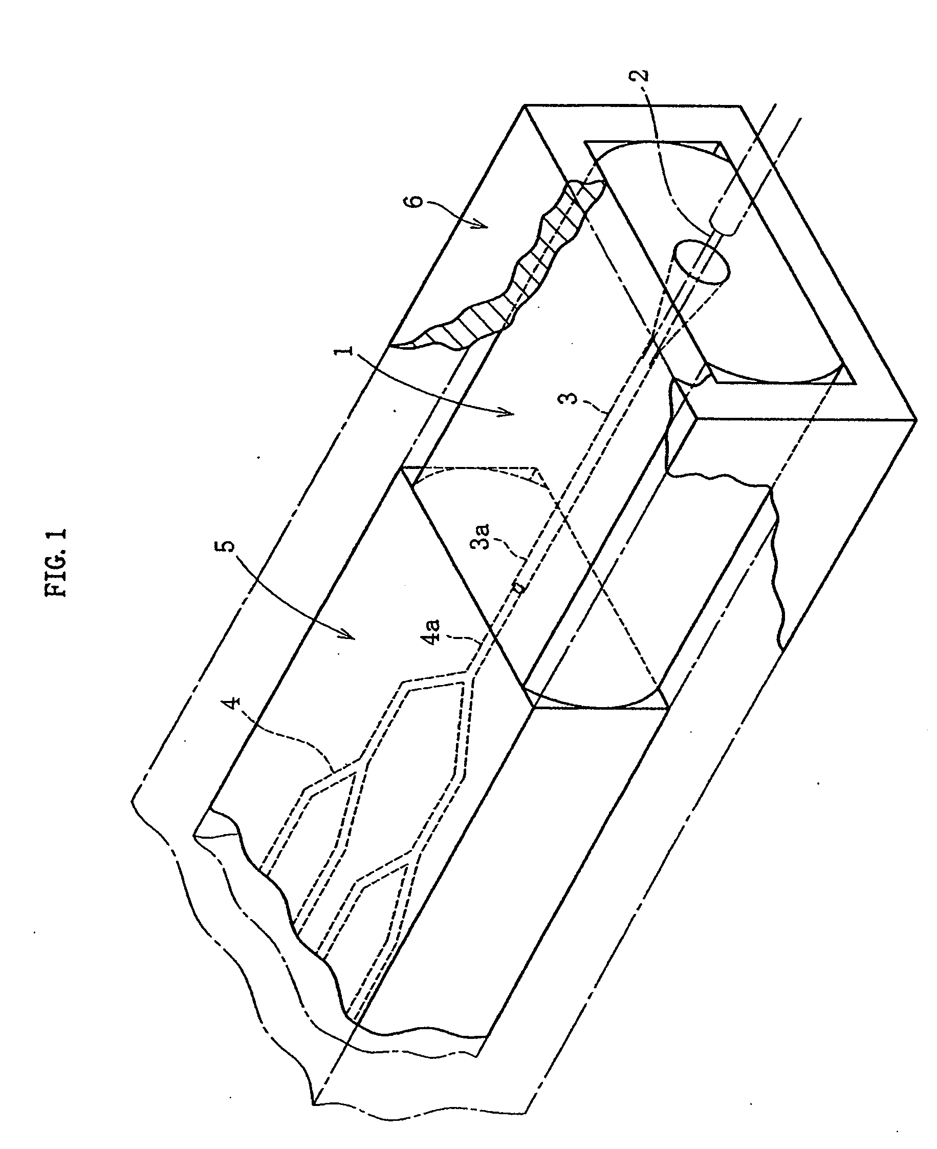
[0044]FIG. 1 represents a glass capillary tube for holding optical fiber and an overview structure of an optical waveguide device as an optical component, which is connected and fixed to the glass capillary tube, related to a first embodiment of the present invention. As illustrated in the same drawing, the glass capillary tube 1 includes an insertion hole 3 through which a single-core optical fiber 2 is inserted and being held within, and an optical waveguide device 5 serving as an optical component with a core 4 is firmly adhered to and in-line with an end (front end) of the optical fiber in the optical axis direction. The firmly adhered glass capillary tube 1 and the optical waveguide device 5 are packaged and housed within a casing (holder) 6. In this case, the front end 3a of the insertion hole 3 in the glass capillary tube 1 and the rear end 4a of the core 4 i...


PUM


Abstract

A glass capillary tube 1 is connected and fixed in a straight line to an optical component 5 having a substantially rectangular cross-section perpendicular to an optical axis 4a. Moreover, a top-surface side end portion 9 and a rear-surface side end portion 8 of an exterior surface 7 of the glass capillary tube 1 are positioned at the same level as the top surface and the rear surface of the exterior surface of the optical component 5 in the height-wise direction, respectively while the central axis of an insertion hole 3, which is provided in the glass capillary tube 1 and into which an optical fiber 2 is inserted and fixed, is matched with the optical axis 4a of the optical component 5.

Description

FIELD OF THE INVENTION [0001] The present invention relates to a capillary tube for holding optical fiber and a connecting structure for optical component, and in particular to a technique for appropriately connecting and fixing a capillary tube for holding optical fiber, in which one or a plurality of insertion holes are formed into which optical fiber is inserted and being held, to an optical component such as an optical waveguide device. BACKGROUND OF THE INVENTION [0002] As is commonly known, glass capillary tube for holding optical fiber (hereinafter, glass capillary tube), in which insertion hole is formed into which optical fiber is inserted and being held, is used for holding optical fiber in alignment with the optical axis of optical component such as optical waveguide-typed device. The glass capillary tube is fixed to an end surface of the optical component in a straight line in such a way that the central axis of the insertion hole and the optical axis of the optical comp...

Claims


Application Information

Patent Timeline
IPC IPC(8): G02B6/00
CPCG02B6/2804G02B6/3801G02B6/30
Inventor TAKEUCHI, HIROKAZUFUNABIKI, NOBUONAKAJIMA, SOTOHIRO
Owner NIPPON ELECTRIC GLASS CO LTD
Why Eureka
Try Eureka