
Pixel data compression and decompression method and device thereof

Active Publication Date: 2007-08-16
NOVATEK MICROELECTRONICS CORP
View PDF12 Cites 11 Cited by
  • Summary
  • Abstract
  • Description
  • Claims
  • Application Information

AI Technical Summary

Benefits of technology

[0009] Accordingly, at least one objective of the present invention is to provide a method for compressing and decompressing pixel data that can reduce video data bandwidth, adjust the difference in the input / output speed of the video data and resolve insufficient memory bus bandwidth problem. In addition, the method can be applied to digital television such as high definition television for processing image data.
[0010] At least another objective of the present invention is to provide a pixel data compression and decompression device that can resolve insufficient memory bus bandwidth problem, adjust the differing input / output speed of the video data and reduce video data bandwidth. Moreover, the pixel data compression and decompression device is adapted to the digital television structure used by high definition televisions.
[0015] Accordingly, the present invention utilizes the quantization of compressed / decompressed pixel data and the control of the flow of data packets to resolve the problem of insufficient memory bandwidth, adjust the difference in the input / output rate of the video data and minimize the video data bandwidth requirement. Furthermore, the present invention is particularly adapted to a broadcasting system having the digital television architecture.

Problems solved by technology

Therefore, the pixel data processing device can directly affect the user's perception of video quality.
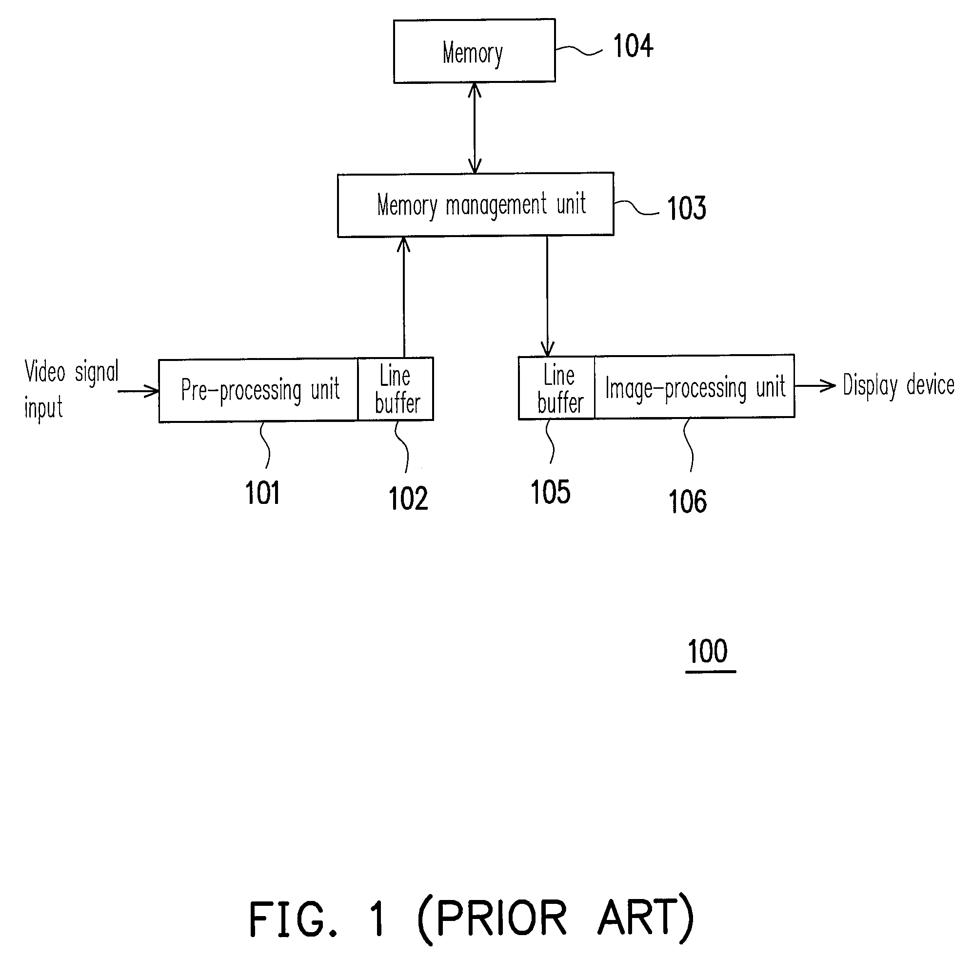
Therefore, the problem of having insufficient frequency bandwidth in the memory management unit 103 is frequently encountered.
Yet, this will increase the production cost significantly.
Other examples, including the U.S. Pat. No. 5,869,198 and U.S. Pat. No. 6,570,626, can reduce the graphic data bandwidth but provide no direct solution to the video data bandwidth problem.

Method used


Image

  • Pixel data compression and decompression method and device thereof
  • Pixel data compression and decompression method and device thereof
  • Pixel data compression and decompression method and device thereof

Examples


Embodiment Construction

[0026] Reference will now be made in detail to the present preferred embodiments of the invention, examples of which are illustrated in the accompanying drawings. Wherever possible, the same reference numbers are used in the drawings and the description to refer to the same or like parts.

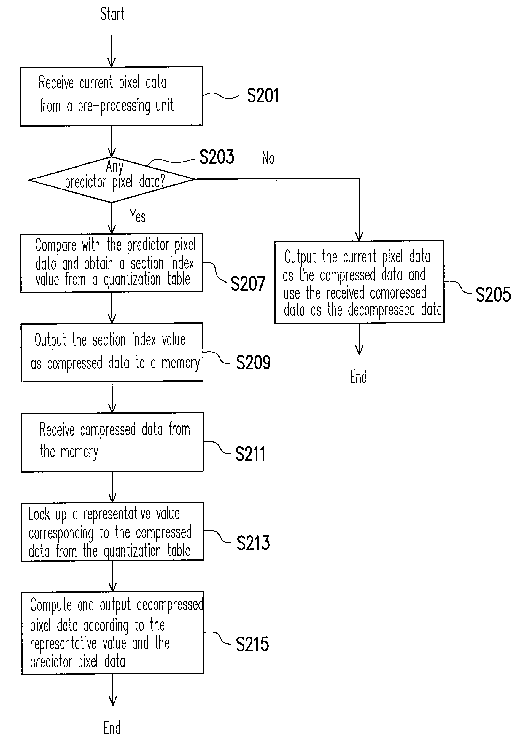
[0027]FIG. 2 is a flow diagram showing the steps for compressing and decompressing pixel data according to one embodiment of the present invention. The present embodiment utilizes conditional differential pulse code modulation (CDPCM) to quantize and compress the image data so that actual number of transmitted bits is reduced. The flow of the packets is also carefully monitored and controlled so that the input and output of video data is optimized for the highest transmission rate. In addition, the CDPCM technique is used to decompress the image data.

[0028] First, in step S201, receive current pixel data from a pre-processing unit. The current pixel data is one component of a color pixel such as r...


PUM


Abstract

The present invention discloses a method for compressing and decompressing pixel data and the device thereof. The method comprises receiving current pixel data from a preprocessor and comparing the current pixel data with predictor pixel data to obtain a section index from a quantization table. Output the section index to a memory as compressed data. Then, receive the compressed data from the memory. Use the quantization table to look up a representative level corresponding to the compressed data and output decompressed pixel data based on the representative level to an image processing unit. The device mentioned above comprises a memory, a compressor and a decompressor. The memory stores compressed data. The compressor quantizes and compresses pixel data and outputs the compressed pixel data to the memory. The decompressor receives the compressed pixel data and decompresses the compressed pixel data and outputs the decompressed pixel data as pixel data.

Description

CROSS-REFERENCE TO RELATED APPLICATION [0001] This application claims the priority benefit of Taiwan application serial no. 95104695, filed Feb. 13, 2006. All disclosure of the Taiwan application is incorporated herein by reference. BACKGROUND OF THE INVENTION [0002] 1. Field of the Invention [0003] The present invention relates to a pixel data compression and decompression method and device thereof. More particularly, the present invention relates to a pixel data compression and decompression method and device thereof applicable to digital television. [0004] 2. Description of the Related Art [0005] In multi-media transmission technology, digital television has become increasingly important. For example, in order to provide a list of multi-media services such as interactive television, television shopping and video-on-demand (VOD) service to every family within the USA, the Federal Communications Commission (FCC) has requested that all televisions produced after 2006 should include ...

Claims


Application Information

Patent Timeline
IPC IPC(8): G06K9/36
CPCH04N19/593H04N19/182H04N19/152H04N19/126
Inventor HU, PO-CHIN
Owner NOVATEK MICROELECTRONICS CORP
Learn More