
Electron gun, cathode ray tube, and projector

a technology electron beam, which is applied in the direction of cathode ray tube/electron beam tube, electric discharge tube, electrical apparatus, etc., can solve the problems of affecting the displaying quality and the worsening of the focusing performance of the crt, so as to prevent the electron beam from deflecting and effectively avoid the interference of the outer electric field

Inactive Publication Date: 2007-08-16
CHUNGHWA PICTURE TUBES LTD
View PDF3 Cites 2 Cited by
  • Summary
  • Abstract
  • Description
  • Claims
  • Application Information

AI Technical Summary

Benefits of technology

[0009] In view of this, the object of the present invention is to provide an electron gun, capable of effectively avoiding the interference of outer electric field with the electron beam inside the focusing electrodes G3 and G4, and of preventing the electron beam from deflecting.
[0010] Another object of the present invention is to provide a cathode ray tube, capable of effectively avoiding the interference of outer electric field with the electron beam inside the focusing electrodes G3 and G4, and of providing better projection quality and focusing performance.
[0011] One another object of the present invention is to provide a projector including an electron gun which is capable of avoiding the interference of outer electric field with the electron beam inside the focusing electrodes G3 and G4 and having better displaying quality.
[0017] Based on the cathode ray tube described above, the present invention further provides a projector which featuring that a plurality of above-mentioned cathode ray tubes capable of emitting different color lights are contained so as to provide the full-color displaying effect.
[0019] In the structure of the electron gun provided by the present invention, the focusing electrode G3 and focusing electrode G4 partly overlap. By doing so, the electric field outside the electron gun can be effectively shielded by the partly overlapped portion of focusing electrodes G3 and G4, and displaying quality of the projector can be effectively improved.

Problems solved by technology

Accordingly, the images to be displayed tend to slur during the projection on the display screen of observers, and focusing performance of the CRT gets worsened and influences displaying quality.

Method used


Image

  • Electron gun, cathode ray tube, and projector
  • Electron gun, cathode ray tube, and projector
  • Electron gun, cathode ray tube, and projector

Examples


Embodiment Construction

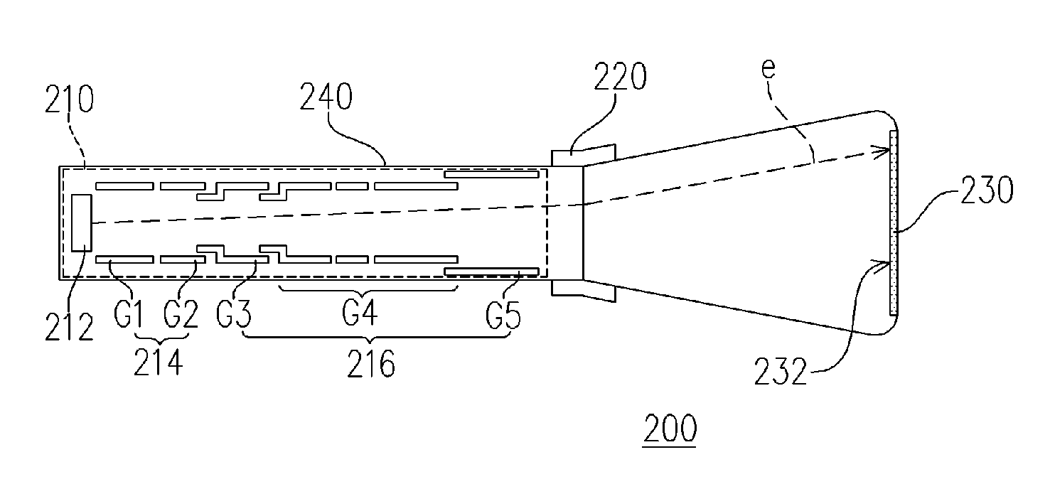
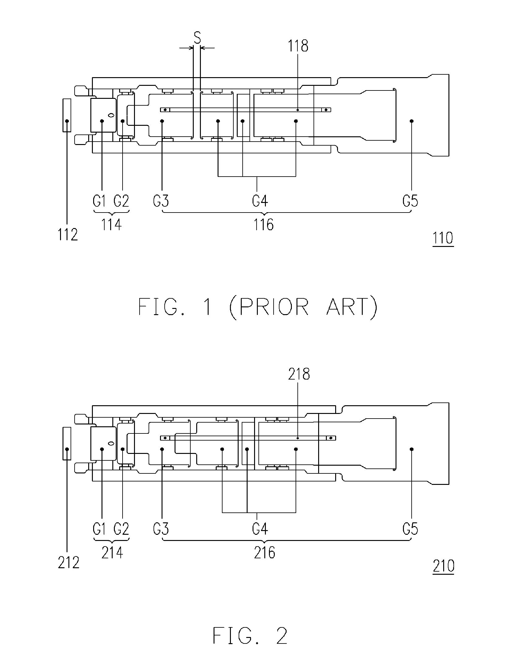
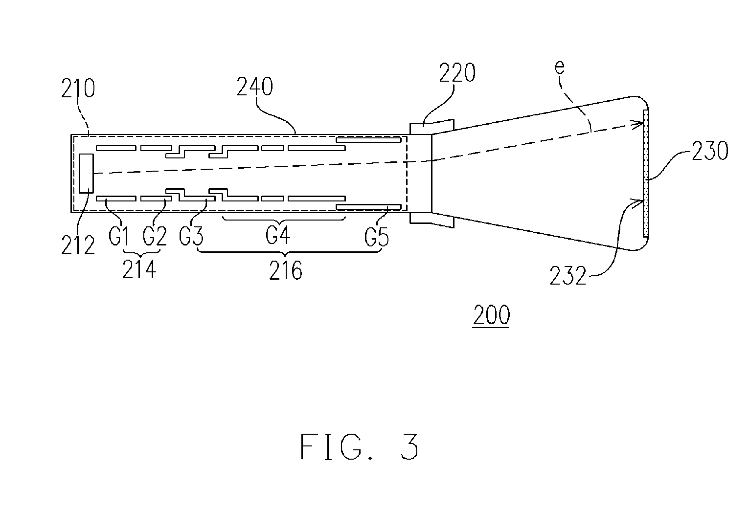
[0025]FIG. 2 schematically shows an electron gun according to one preferred embodiment of the present invention. As seen in FIG. 2, the electron gun 210 of the present invention mainly comprises a cathode 212, a beam forming region 214, an electron lens region 216, and a high voltage wire 218. The cathode 212 can produce a plurality of electrons with energy. The beam forming region 214 is disposed behind the cathode 212 and it sequentially includes the control electrode G1 and screen electrode G2. When passing through the control electrode G1 and the screen electrode G2, the electrons produced by the cathode 212 are focused as an electron beam. Besides, the electron lens region 216 is adjacent to the beam forming region 214 and it sequentially includes a focusing electrode G3, a focusing electrode G4 and a focusing electrode G5 where the focusing electrode G3 and focusing electrode G4 partly overlap.

[0026] Also referring to FIG. 2, one end of the focusing electrode G4 adjacent to f...


PUM


Abstract

An electron gun including a cathode, a beam forming region, an electron lens region, and a high voltage wire is provided. The beam forming region is disposed behind the cathode to make the electrons produced by the cathode become an electron beam. The beam forming region has a control electrode G1 and a screen electrode G2 sequentially. In addition, the electron lens region is adjacent to the beam forming region. The electron lens region has a focusing electrode G3, a focusing electrode G4, and a focusing electrode G5, wherein the focusing electrode G3 and the focusing electrode G4 overlap. Moreover, the high voltage wire is disposed in the electron lens region to connect the focusing electrode G3 and the focusing electrode G5. A cathode ray tube and a projector applying the electron gun are also provided.

Description

BACKGROUND OF THE INVENTION [0001] 1. Field of Invention [0002] The present invention relates to a display device. More particularly, the present invention relates to the structure design of the cathode ray tube of the CRT projector and the electron gun thereof. [0003] 2. Description of Related Art [0004] Along with development of the multi-media, the display, served as the interface in communication between people and information becomes much more dominant day after day. In addition to the front-type projection display on which the cathode ray tube (CRT) technique is applied, such as home-use television, monitor and computer screen, another rear-type projection display in which the built-in optical engine and certain optical designs are employed also turns mature gradually for rendering larger display images. [0005] In general, due to having the traits of high brightness and minor volumes, the CRT projectors using rear projection technique are widely used in the occasions where the...

Claims


Application Information

Patent Timeline
Patent Type & Authority Applications(United States)
IPC IPC(8): H01J29/50H01J29/46
CPCH01J29/503H01J2229/4824H01J2229/481
Inventor CHANG, WEN NINGWANG, CHI-TSAN
Owner CHUNGHWA PICTURE TUBES LTD
Learn More