
Interstitial microwave system and method for thermal treatment of diseases

Inactive Publication Date: 2007-08-09
MMTC LTD +1
View PDF25 Cites 140 Cited by
  • Summary
  • Abstract
  • Description
  • Claims
  • Application Information

AI Technical Summary

Problems solved by technology

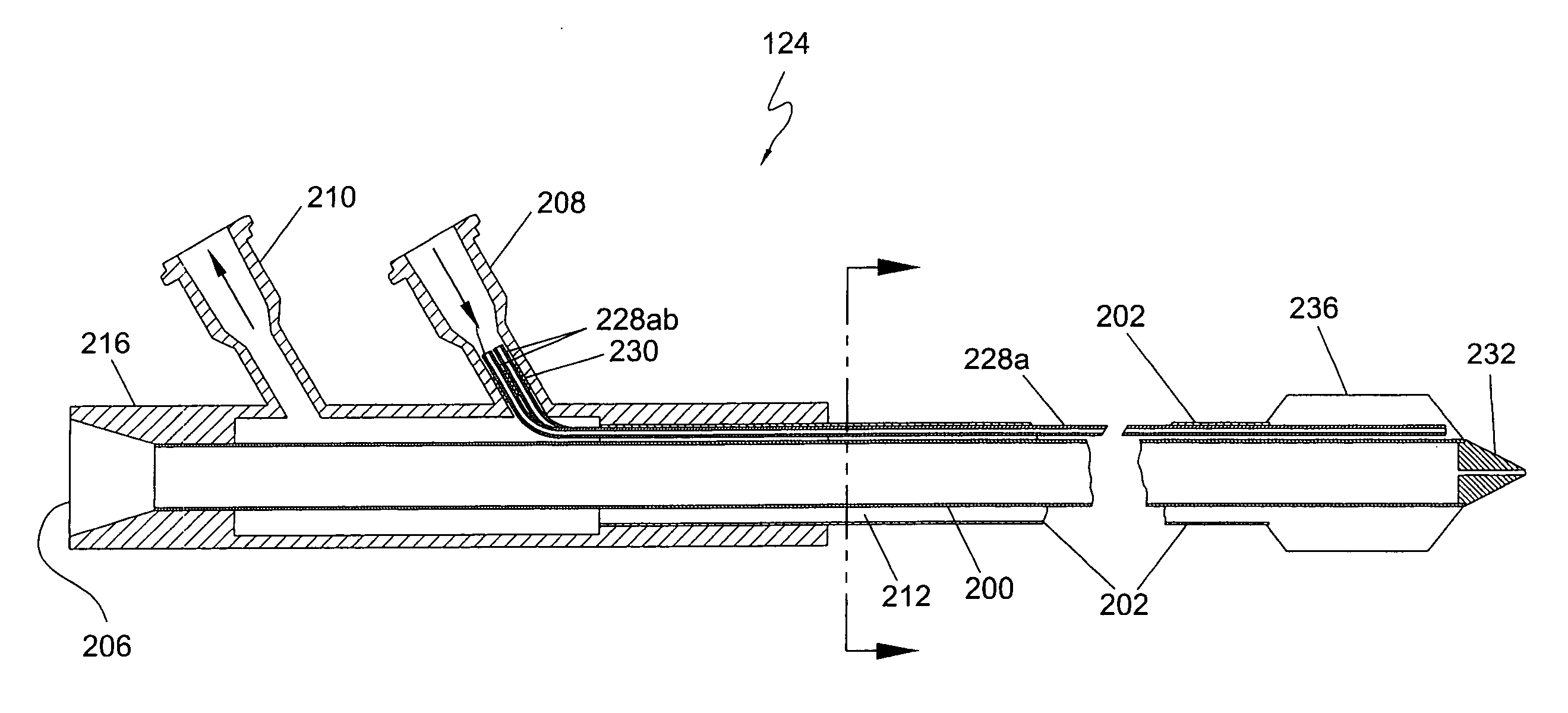
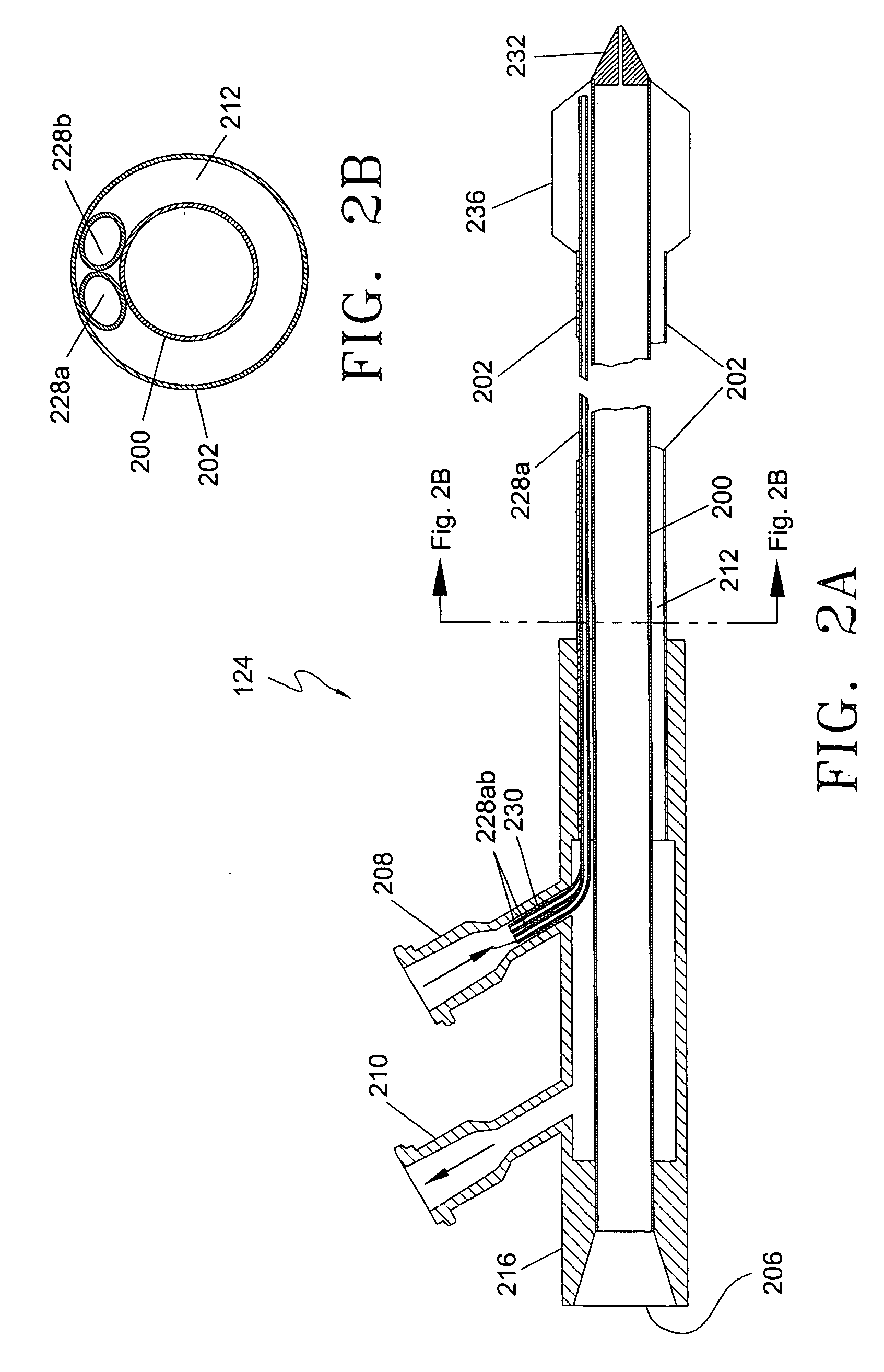
Because the insertion-sleeve assembly may lack stiffness (if comprised of thin plastic tubing attached to a distally-located plastic penetrating point), the assembly may require that a rigid rod be inserted in the sleeve assembly to permit it to pierce the patient's skin and push through the underlying sub-cutaneous tissue to reach the diseased tissue.

Method used


Image

  • Interstitial microwave system and method for thermal treatment of diseases
  • Interstitial microwave system and method for thermal treatment of diseases
  • Interstitial microwave system and method for thermal treatment of diseases

Examples


Embodiment Construction

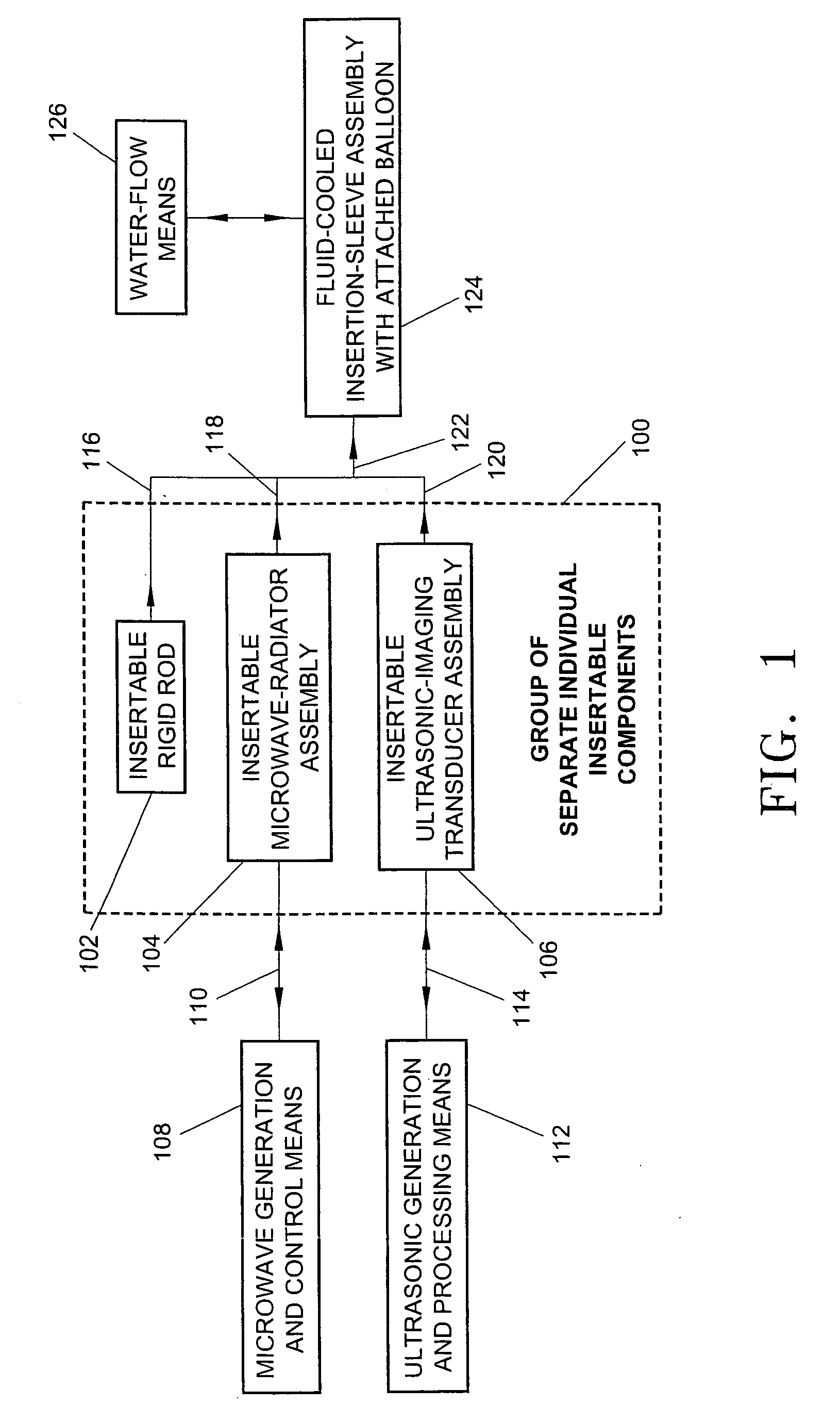
[0014] Referring to the FIG. 1 functional block diagram, there is shown a group of separate individual insertable components 100, which comprises insertable rigid rod 102, insertable microwave-radiator assembly 104 and insertable ultrasonic-imaging transducer assembly 106. Microwave energy from microwave generation and control means 108 is supplied to insertable microwave-radiator assembly 104 through connection 110. In practice, connection 110 normally comprises a standard 50 ohm impedance coaxial cable. Ultrasonic energy from ultrasonic generation and processing means 112 is supplied to insertable ultrasonic-imaging transducer assembly 106 through connection 114.

[0015] As indicated by arrows 116, 118, 120 and 122, at any one time, any selected one of insertable rigid rod 102, insertable microwave-radiator assembly 104 or insertable ultrasonic-imaging transducer assembly 106 may be inserted in minimally-invasive water-cooled insertion-sleeve assembly with attached balloon 124. In ...


PUM


Abstract

A minimally-invasive fluid-cooled insertion sleeve assembly, with an attached balloon and distally-located penetrating tip, into which sleeve any of a group comprising a rigid rod, a microwave-radiator assembly and an ultrasonic-imaging transducer assembly may be inserted, constitutes a probe of the system. The sleeve assembly comprises spaced inner and outer plastic tubes with two fluid channels situated within the coaxial lumen between the inner and outer tubes. The fluid coolant input flows through the fluid channels into the balloon, thereby inflating the balloon, and then exits through that coaxial lumen. An alternative embodiment has no balloon. The method employs the probe for piercing sub-cutaneous tissue and then ablating deep-seated tumor tissue with microwave-radiation generated heat.

Description

BACKGROUND [0001] 1. Field of the Invention [0002] This invention relates to an interstitial microwave system and method employing a minimally-invasive probe for thermally treating diseased tissue of a patient and, more particularly, to a probe comprising a fluid-coolable insertion-sleeve assembly into which any one of a plurality of separate functional structures may be inserted. [0003] 2. Description of the Prior Art [0004] Incorporated by reference herein is U.S. Pat. No. 6,312,428 B1, issued Nov. 6, 2001, which discloses an interstitial system employing a minimally-invasive probe or thermally treating diseased tissue of a patient, but the system is not a microwave system and its probe comprises an integral structure that is not fluid cooled. Further, incorporated by reference herein is U.S. Pat. No. 6,847,848, issued January 2005 and assigned to the same assignee as the present application, which discloses an interstitial microwave system employing a minimally-invasive catheter ...

Claims


Application Information

Patent Timeline
Patent Type & Authority Applications(United States)
IPC IPC(8): A61F2/00A61N1/00
CPCA61B18/18A61N2005/007A61N5/045A61B18/1815
Inventor APPLING, WILLIAM M.DI PALMA, GIORGIOSTERZER, FREDMAWHINNEY, DANIEL D.
Owner MMTC LTD
Learn More