Process for amplifying DNA

a technology of amplifying dna and amplifying dna, which is applied in the field of amplifying dna, can solve the problems of sequences including this type of positions that are often unsuitable for primers, sequences that are impractical for primer use, and the efficiency of amplification deterioration, so as to improve the efficiency and specificity of dna amplification, improve the efficiency and specificity of amplification, and simplify the preliminary tests of ann

Inactive Publication Date: 2007-08-09
NICHIREI CORP
View PDF5 Cites 0 Cited by
  • Summary
  • Abstract
  • Description
  • Claims
  • Application Information

AI Technical Summary

Benefits of technology

[0008] The inventors of the present invention discovered an extremely surprising fact. Namely, when a compound such as LC-Red 705, to the 5′ terminus of the degenerate primer, then the PCR amplification efficiency and specificity could be improved, resulting in an improvement in the efficiency and specificity of the DNA amplification reaction, and the inventors were hence able to complete the present invention. The optimum temperature range for annealing could be widened, meaning the preliminary tests for investigating the annealing conditions could be simplified, the overall process could be simplified considerably.

Problems solved by technology

Unfortunately, sequences including this type of position are frequently unsuitable as primers.
In other words, in cases in which, for example, the AT content is extremely high, or the forward and reverse melting temperatures (Tm) do not match, the efficiency of the amplification deteriorates, making the sequence impractical for use as a primer.
This problem becomes a considerable drawback in cases in which very small quantities of DNA need to be detected.

Method used


Image

  • Process for amplifying DNA
  • Process for amplifying DNA

Examples


example 1

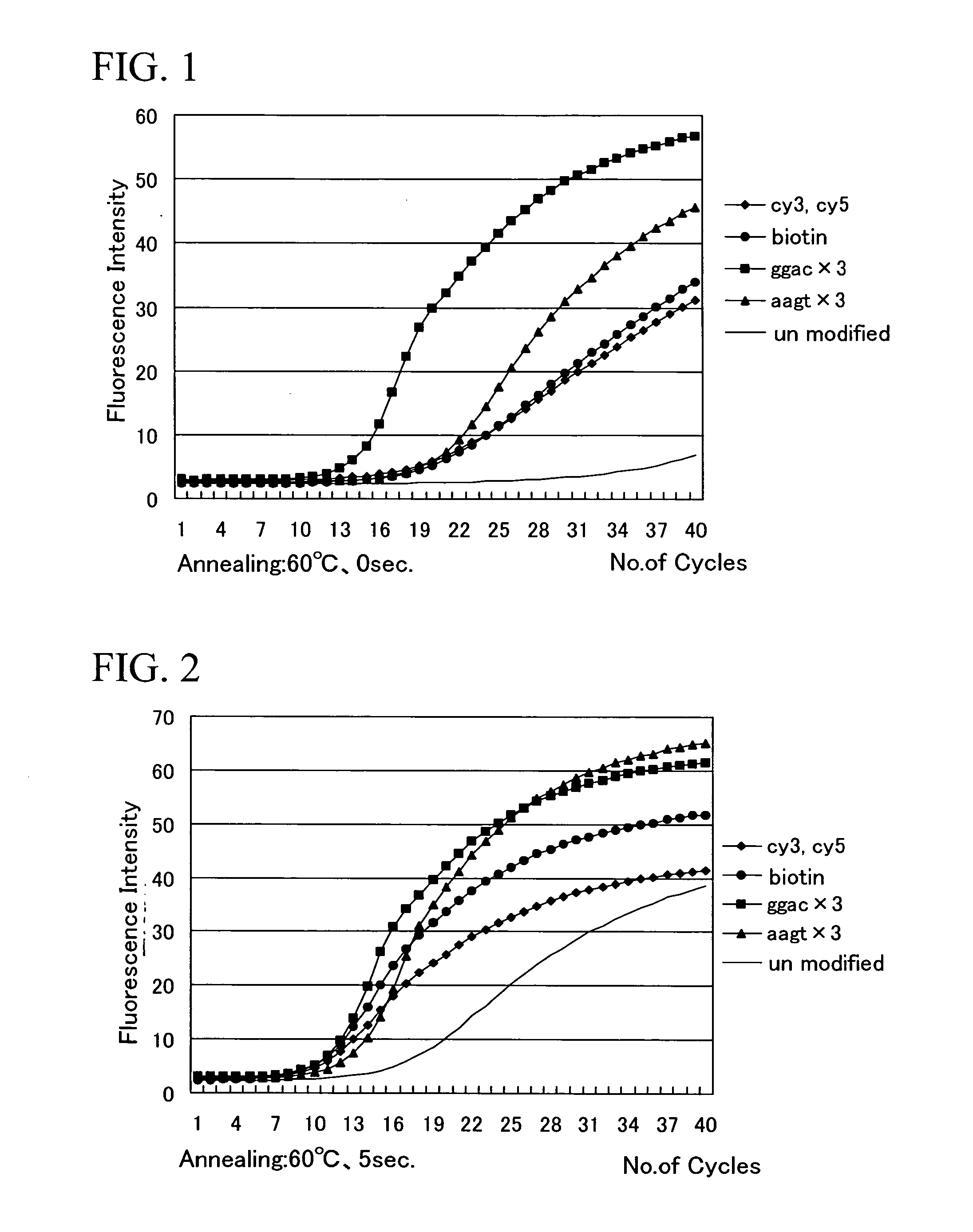
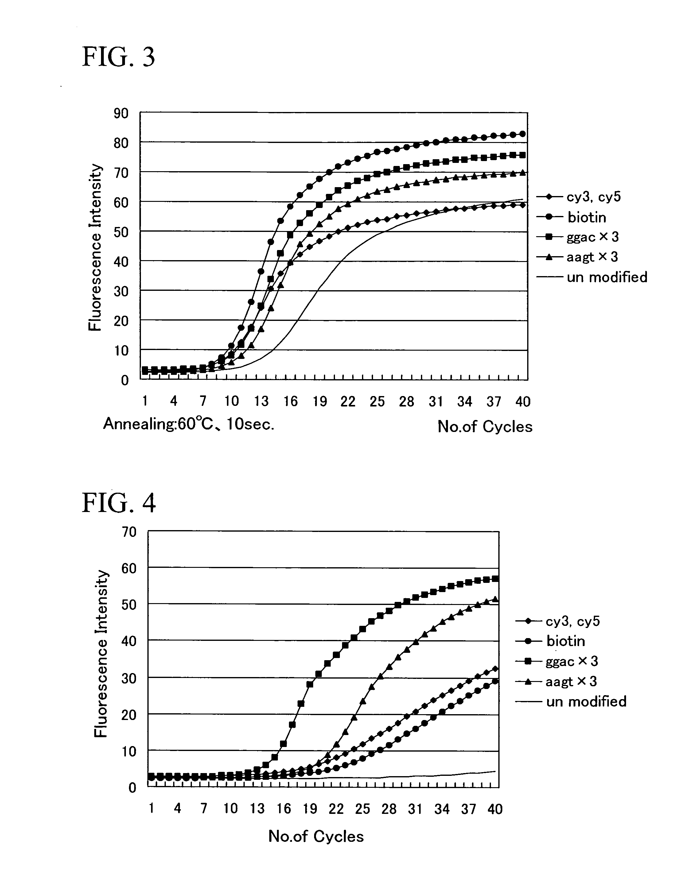
Comparison of the Upper Limit Annealing Temperature for Amplification

[0049] Using primers for the detection of Vibrio parahaemolyticus with a compound selected from the specified compounds group conjugated to the 5′ terminus, and utilizing a PCR Express device manufactured by Hybaid Co., Ltd with a Gradient Block Module added, the upper limit annealing temperature for amplification was measured by conducting PCR under the conditions described below.

[0050] The primers for the detection of Vibrio parahaemolyticus utilized a nucleotide sequence represented by the sequence number 1 as the forward side primer and a nucleotide sequence represented by the sequence number 2 as the reverse side primer. [0051] Sequence number 1: aagaagacct agaagatgat [0052] Sequence number 2: gttaccagta atagggca

Each of the compounds of the specified compounds group shown in Table 1 was conjugated to the 5′ termini of the forward side primer and the reverse side primer. In a separate preparation, chromoso...

example 2

Investigation of the Amplification Efficiency in Primers Containing a Compound Selected from the Specified Compounds Group Added to the 5′ Terminus

[0058] A nucleotide sequence represented by the sequence number 1 was used as the forward side primer and a nucleotide sequence represented by the sequence number 2 was used as the reverse side primer. Either cy3, cy5, or biotin, were added (conjugated) to the 5′ termini of the forward side primer and the reverse side primer, and the kinetics of the amplification reaction were analyzed by conducting real time PCR under conditions described below, using a Light Cycler System (manufactured by Roche Diagnostics Co., Ltd.), and using chromosome DNA extracted from a type strain (IFO12711T) of Vibrio parahaemolyticus as a template.

[0059] The PCR conditions were as follows. (1) Denaturation: 1.5 minutes at 95° C. (2) Denaturation: 0 seconds at 95° C. (3) Annealing: 0, 5 or 10 seconds at 60° C., or 5 seconds at 64° C. (4) Extension reaction: 1...


PUM

PropertyMeasurementUnit
Temperatureaaaaaaaaaa

Abstract

The present invention has an object of providing a process for amplifying DNA. The present invention provides a process for amplifying DNA, comprising providing a primer in which a compound such as LC-Red 705 is added to the 5′ terminus; and amplifying said target DNA fragment via PCR using said PCR primer, in which annealing is carried out at the temperature higher than normal PCR reaction, and / or with the annealing time shorter than normal PCR reaction

Description

CROSS REFERENCE TO RELATED APPLICATIONS [0001] This application is a Continuation-in-Part of U.S. patent application Ser. No. 10 / 601,713, filed Jun. 20, 2003, which claims priority from Applications filed in Japan on Jan. 10, 2002, No. 2002-003912 respectively.BACKGROUND OF THE INVENTION [0002] 1. Field of the Invention [0003] The present invention relates to a process for amplifying DNA. [0004] 2. Description of Related Art [0005] DNA amplification is extremely important in the detection of genes, and within the field of DNA amplification, the PCR method enables a large amplification of a targeted portion of nucleotide sequences within the DNA, and is a method which is used not only within biotechnology, but also within a variety of other fields. [0006] However, when a specific detection primer is designed, the primer must include a base position specific to the target sequence. [0007] Unfortunately, sequences including this type of position are frequently unsuitable as primers. In...

Claims


Application Information

Patent Timeline
IPC IPC(8): C12Q1/68C12P19/34C07H21/04
CPCC12Q1/686C12Q2561/113C12Q2527/101
Inventor KOIZUMI, TAKESHIHAMANO, YOKOYAMAMOTO, SATOSHI
Owner NICHIREI CORP
Why Eureka
Try Eureka