
Sealed cover for recessed lighting fixture

Inactive Publication Date: 2007-08-09
ROBSON CHRISTOPHER MARK
View PDF9 Cites 34 Cited by
  • Summary
  • Abstract
  • Description
  • Claims
  • Application Information

AI Technical Summary

Benefits of technology

[0017] It is therefore an object of the present invention to provide a cover for a RLF which provides an airtight seal between said fixture and the inhabitable space below.
[0018] Another object of the present invention is to promote energy conservation by preventing energy loss from the living space, through the RLF.
[0019] Still another object of the present invention is to promote energy conservation by promoting conversion of the light source in the RLF from incandescent bulbs to CFBs, a conversion which is made more appealing where the CFB is concealed by the cover.
[0021] A final object of the present invention is to provide an aesthetic improvement to RLFs by creating a smooth and uniform appearance to the visible portion of the fixture, and concealing aspects of the RLF which are do not appeal to the user (e.g. a discolored RLF trim ring or black baffle).

Problems solved by technology

RLFs pose energy-loss concerns: because RLFs are particularly pervasive in older homes with outmoded attic insulation, and because the very nature of a RLF is to perforate the barrier between the attic and the living space below, a situation is created whereby interior climate control efficiency is sacrificed: in the winter, furnace-heated warm air rises to the ceiling and is drawn through the RLF out of the living space, decreasing furnace efficiency and increasing home-heating costs.
In warm weather, air conditioned cool air is similarly drawn away from the living space, thereby decreasing air conditioner efficiency and increasing electricity costs.
Concerns surrounding such energy inefficiency intensify proportionately with a rise in energy prices.
In addition to energy loss due to design, RLFs often fail to take advantage of efficiencies resulting from advances in lighting technology: because the light bulb used in an RLF is visible (though it may be recessed), RLFs are generally not good candidates for higher-efficiency compact fluorescent bulbs (which became widely available in the late 1990s, and were not contemplated at the time of installation of many RLFs currently in use worldwide).
The vastly longer life of CFBs compared to incandescent bulbs is of particular importance when it comes to a ceiling-mounted RLF, as the bulbs in such fixtures are particularly difficult and potentially dangerous to replace.
In addition to the deleterious energy effects of RLFs outlined above, RLFs also result in an undesirable entry point into the living space for insects and other pests.
Though an occupant may do everything possible to seal windows, doors and walls against such entry, RLFs are less easy to secure.
U.S. Pat. Application No. 20030186017 filed by Stockton discloses a RLF insert which prevents paint or drywall texture from entering and adhering to the fixture, but is not intended for permanent use with an RLF, and is not intended for use during operation of the RLF.
The prior art fails to disclose a RLF cover which provides an airtight seal around the visible portion of said RLF, designed to streamline the appearance of the RLF and permit conversion to energy-saving light sources, while simultaneously preventing energy loss and insect entry through the opening required for installation and operation of the RLF.

Method used


Image

  • Sealed cover for recessed lighting fixture
  • Sealed cover for recessed lighting fixture
  • Sealed cover for recessed lighting fixture

Examples


Embodiment Construction

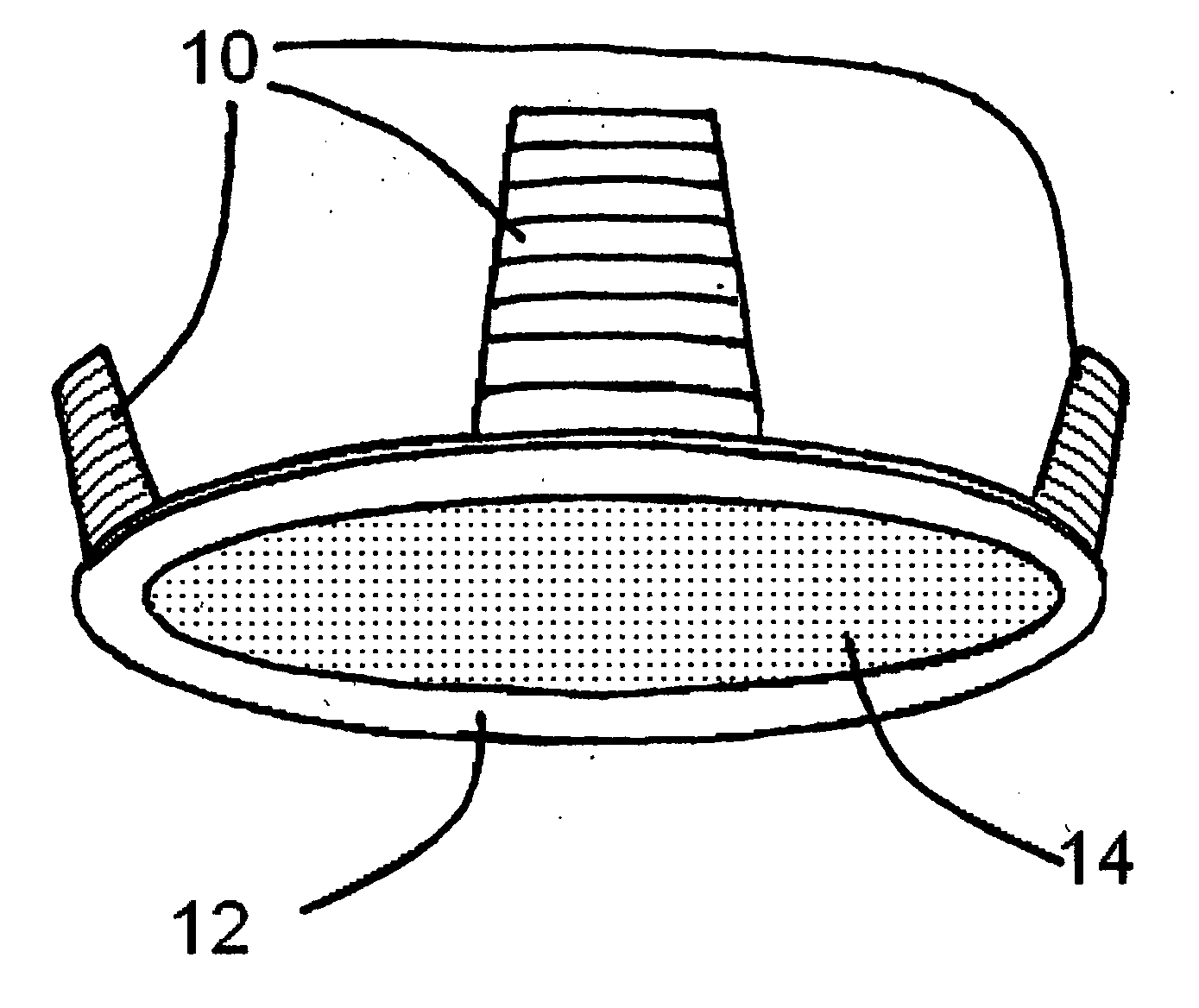
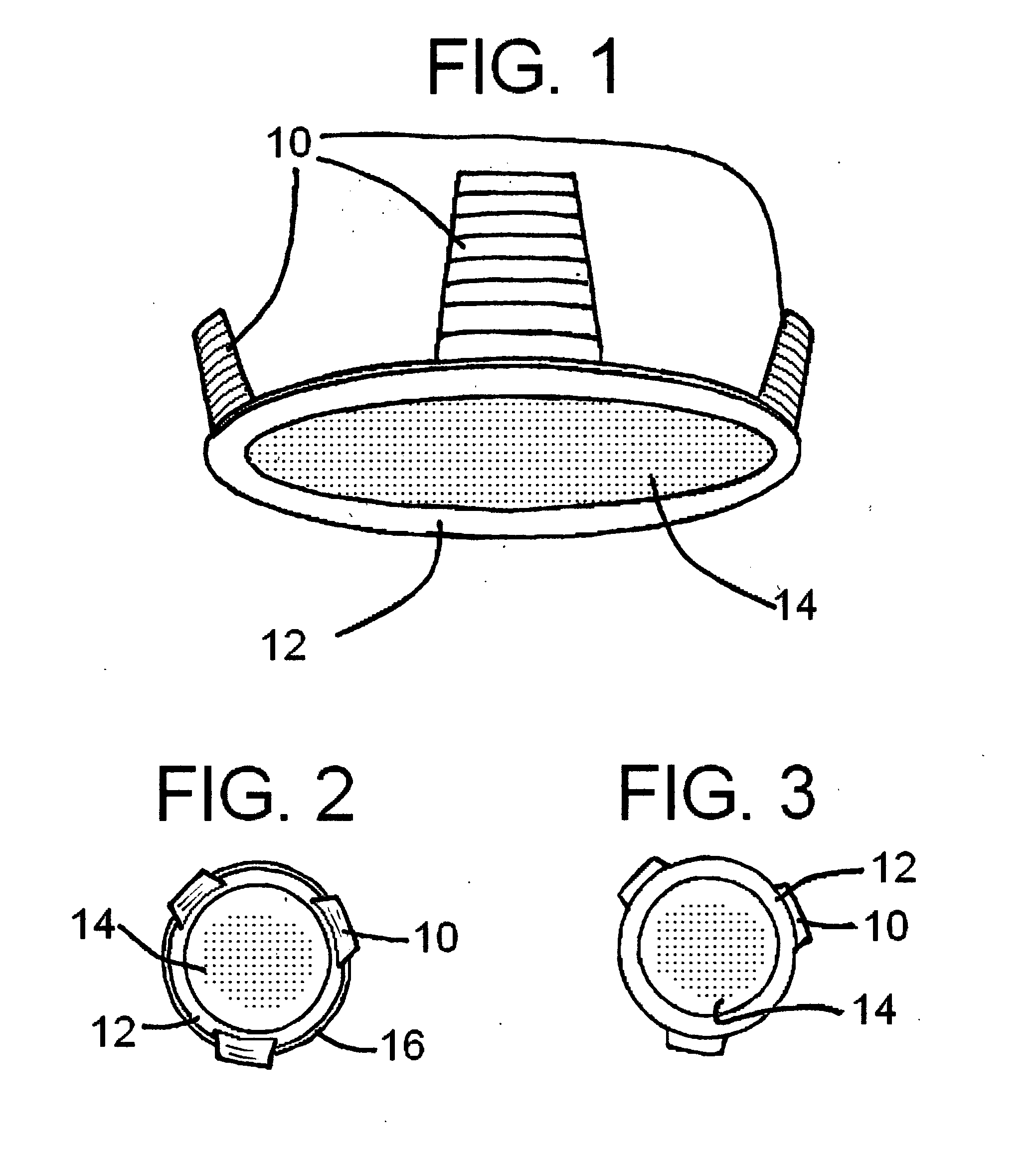
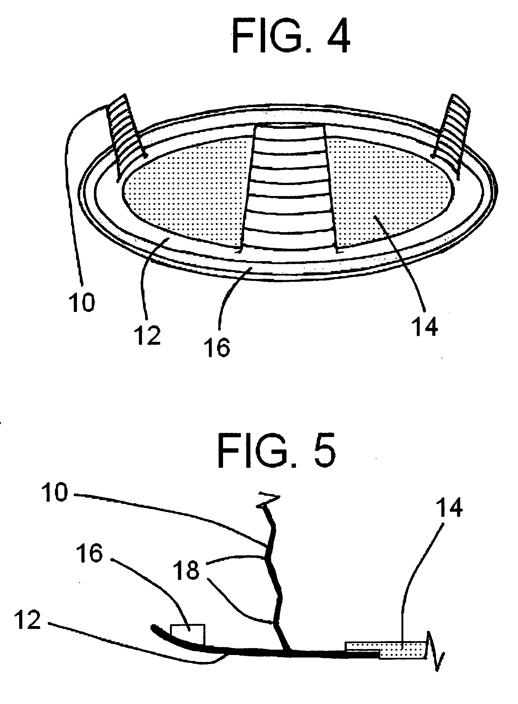
[0038] The present invention allows for the quick and simple installation of an airtight cover over a RLF without special skills, tools, dexterity or physical strength. In its most basic form, the present invention consists of an insert that is engaged with the RLF at three points, namely (i) the housing of the present invention frictionally engaged with the inner surface of the RLF baffle, (ii) the outer trim of the present invention physically engaged with the outer trim of the RLF, and (iii) the airtight seal ring adhesively engaged with the trim ring of the present invention, and physically engaged with the outer trim of the existing RLF. As contained herein, the present invention is described with reference to a ceiling-mounted RLF, though it is to be understood that use with other fixtures having similarly defined openings is expressly contemplated.

[0039]FIG. 1 is a perspective view from the underside of the present invention depicting the retaining clips of the housing 10, t...


PUM


Abstract

The present invention relates to a cover for a recessed light fixture, having a housing composed of heat-tolerant material, and having visible trim ring (12), and a means for retaining said cover to said fixture (10). Light generated by the recessed light fixture will pass through the lens (14), which may be transparent, translucent, or colored. The present invention is sized to fit within the baffle of a preexisting recessed light fixture (15), to which the present invention may be frictionally engaged, and over the outer trim of such a fixture (17), to which the present invention will form an airtight seal through the use of a seal ring (16). The present invention seeks to promote energy efficiency by providing an airtight barrier which inhibits the passage of conditioned (furnace-heated or air conditioner-cooled) air through the recessed light fixture and out of the living space. Energy efficiency is also promoted by encouraging (though not necessitating) conversion from incandescent bulbs to compact fluorescent bulbs. Further, the airtight barrier has the desirable effect of prohibiting the movement of insects through the recessed light fixture and into the living space. The present invention can be easily installed without tools or special skill, and can be easily removed to allow for bulb replacement. It can be manufactured in varying shapes and sizes, including sizes conforming to standard recessed light fixtures having circular openings with 4-inch and 6-inch diameters, and with tapered and non-tapered baffles.

Description

CROSS-REFERENCE TO RELATED APPLICATIONS [0001] Not applicable. STATEMENT REGARDING FEDERALLY SPONSORED RESEARCH AND DEVELOPMENT [0002] Not Applicable. REFERENCE TO SEQUENCE LISTING, A TABLE, OR A COMPUTER PROGRAM LISTING COMPACT DISC APPENDIX [0003] Not Applicable. BACKGROUND OF THE INVENTION [0004] The present invention relates to a cover, sized to fit within and engage the baffle of a recessed lighting fixture, and extending to the outer rim of said fixture, forming an airtight seal thereupon. [0005] A recessed light fixture (referred to herein as a “RLF”) is one housed within a can located within an attic (in the case of a ceiling-mounted RLF), with only the trim and light bulb generally visible beneath. RLF popularity from the 1960s to the present derive from their unobtrusiveness into the living space, aesthetics (or lack thereof), and their utility in allowing light to be focused in a desired area [0006] RLFs pose energy-loss concerns: because RLFs are particularly pervasive i...

Claims


Application Information

Patent Timeline
IPC IPC(8): F21V29/00
CPCF21S8/026F21V3/04Y02B20/386F21V17/164F21V31/00F21V15/01Y02B20/30
Inventor ROBSON, CHRISTOPHER MARK
Owner ROBSON CHRISTOPHER MARK
Learn More