
Implantable electrodes having zirconium nitride coatings

Active Publication Date: 2007-08-02
MEDTRONIC INC
View PDF40 Cites 6 Cited by
  • Summary
  • Abstract
  • Description
  • Claims
  • Application Information

AI Technical Summary

Benefits of technology

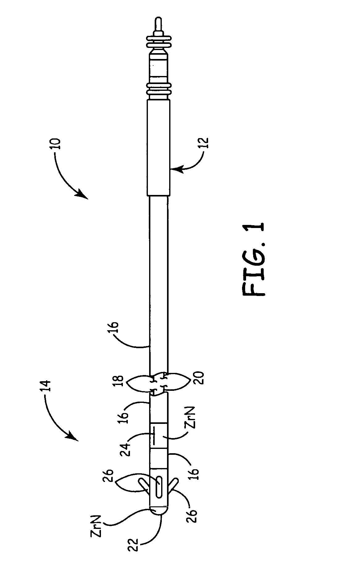
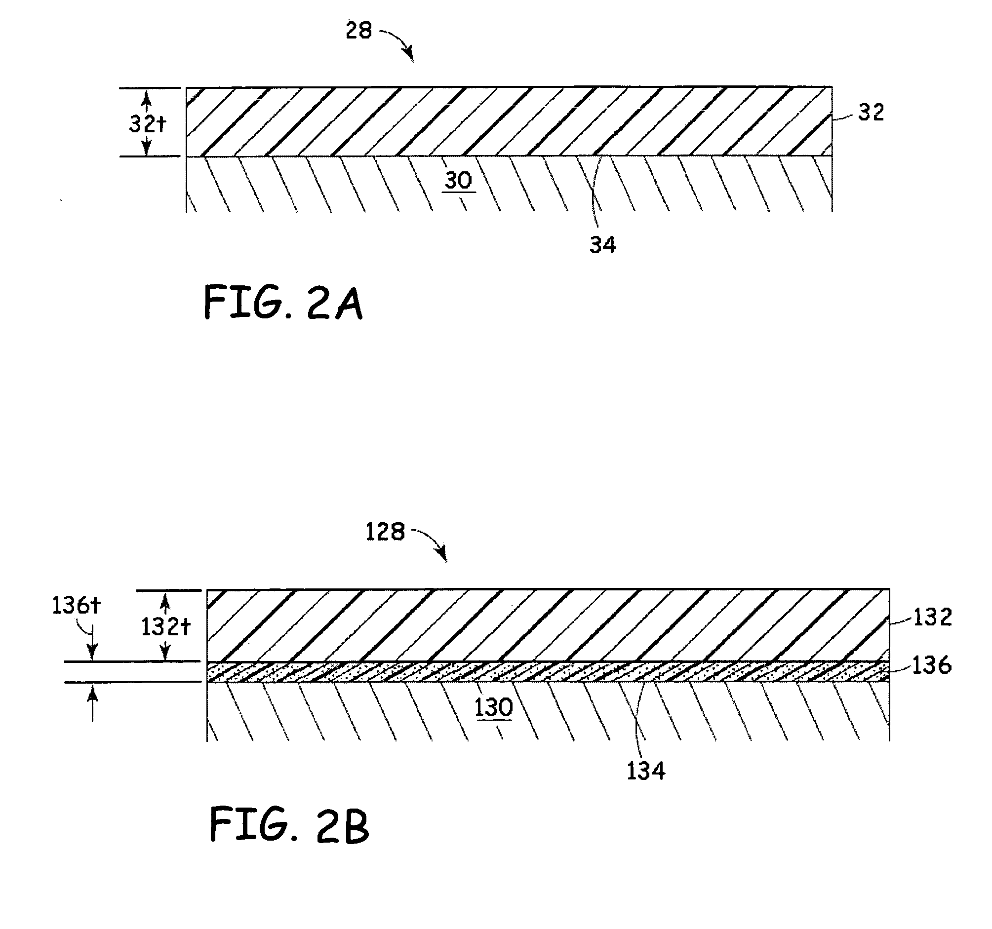
[0003] The present invention relates to an implantable medical electrode and a method of fabricating the implantable medical electrode. The implantable medical electrode includes an electrode substrate having an exterior surface, and a zirconium nitride (ZrN) coating disposed over the exterior surface of the electrode substrate. The ZrN coating reduces post-stimulation polarization on the implantable medical electrode, thereby improving stimulation and sensing capabilities.

Problems solved by technology

This post-stimulation polarization may interfere with subsequent sensing of signals, such as intrinsic cardiac activity signals.

Method used


Image

  • Implantable electrodes having zirconium nitride coatings
  • Implantable electrodes having zirconium nitride coatings
  • Implantable electrodes having zirconium nitride coatings

Examples


examples

[0025] The present invention is more particularly described in the following examples that are intended as illustrations only, since numerous modifications and variations within the scope of the present invention will be apparent to those skilled in the art. Unless otherwise noted, all parts and reagents used in the examples were obtained, or are available, from the standard suppliers, or may be synthesized by conventional techniques.

[0026] Coated electrodes of Examples 1-13 were each prepared by electrochemically depositing zirconium ions and nitrogen ions onto a titanium electrode under varying processing conditions to form a zirconium nitride coating over the titanium electrode. The electrochemical deposition involved sputtering from a zirconium target in the presence of a nitrogen-argon gas atmosphere. The sputtering system used was a trade designated “PerkinElmer 2400” Sputtering System, which is commercially available from PerkinElmer, Inc., Shelton, Conn., and which was modi...


PUM


Abstract

An implantable medical electrode comprising an electrode substrate having an exterior surface, and a zirconium nitride coating disposed over the exterior surface.

Description

BACKGROUND OF THE INVENTION [0001] The present invention generally relates to implantable electrodes, and more particularly to implantable sensing and stimulating electrodes having reduced post-stimulation polarization. [0002] Following delivery of stimulation (e.g., a cardiac pacing pulse), an electrode surface typically retains an accumulation of charge that persists for a period of time thereafter. This post-stimulation polarization may interfere with subsequent sensing of signals, such as intrinsic cardiac activity signals. This issue has been addressed in a number of ways over the years. One common approach to reducing post-stimulation polarization is to provide a high-surface area coating having a micron or sub-micron sized topography, such as a porous sintered metallic coating, a metal oxide coating, or a coating of platinum black. However, further development in post-stimulation polarization levels is desirable. BRIEF SUMMARY OF THE INVENTION [0003] The present invention rel...

Claims


Application Information

Patent Timeline
IPC IPC(8): A61B5/04
CPCA61B5/042A61N1/3716A61N1/056A61B5/283
Inventor NYGREN, LEA A.KNOWLES, SHAWN D.
Owner MEDTRONIC INC
Learn More