Refrigerant compressor

Inactive Publication Date: 2007-08-02
TOYOTA IND CORP
View PDF2 Cites 5 Cited by
  • Summary
  • Abstract
  • Description
  • Claims
  • Application Information

AI Technical Summary

Problems solved by technology

This enlargement of the rear housing results in increase in size of the refrigerant compressor.

Method used


Image

  • Refrigerant compressor
  • Refrigerant compressor
  • Refrigerant compressor

Examples


Embodiment Construction

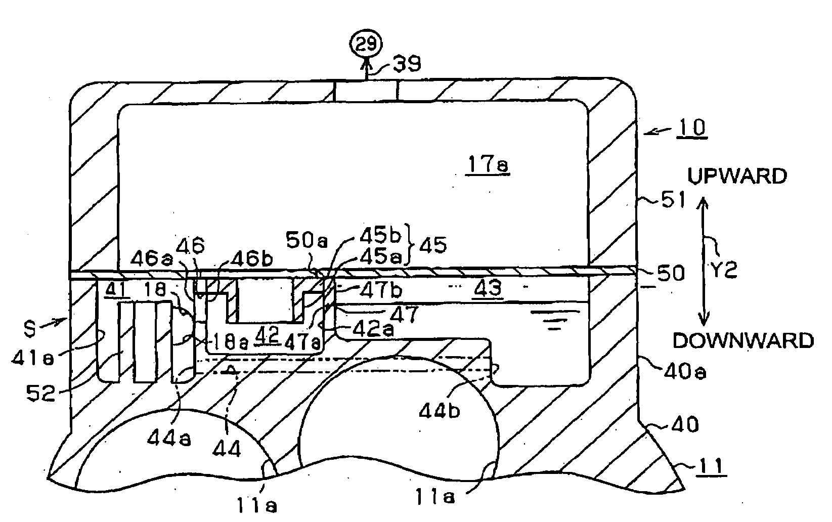
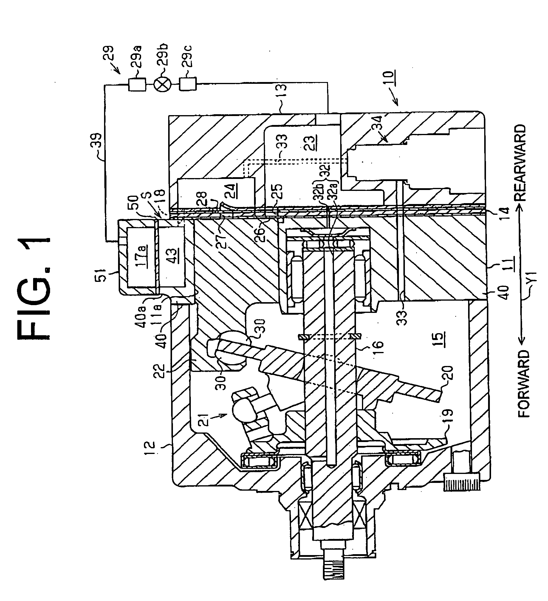
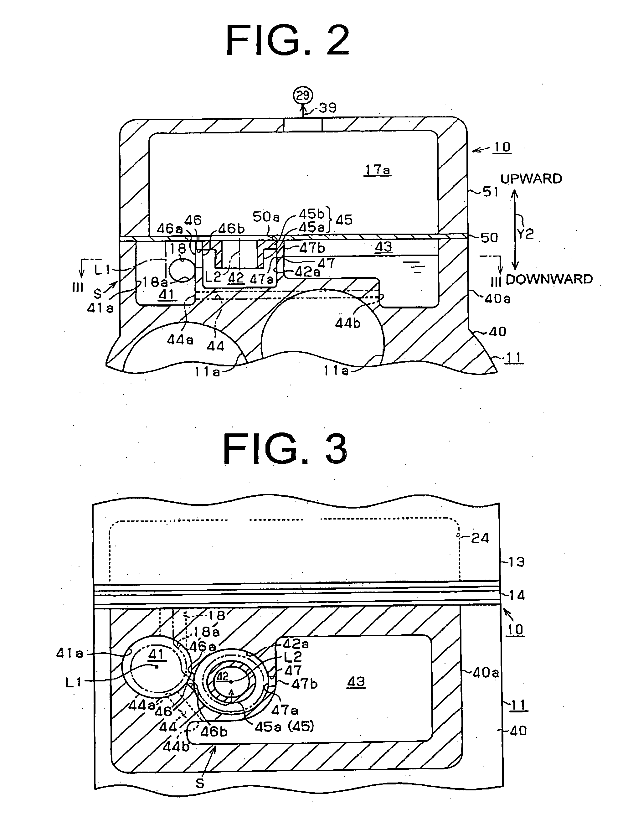
[0014]An embodiment of a variable displacement swash plate compressor for vehicle air conditioners according to the refrigerant compressor of the present invention will now be described with reference to FIGS. 1 to 3. In the following description, the direction of arrow Y1 shown in FIG. 1 corresponds to the “front” and “rear” (longitudinal) direction of the variable displacement swash plate compressor, and the direction of arrow Y2 shown in FIG. 2 corresponds to the “upper” and “lower” (vertical) direction thereof.

[0015]As shown in FIG. 1, the housing of the variable displacement swash plate compressor (hereinafter referred to simply as a “compressor”) 10 includes a cylinder block 11, a front housing 12 fixedly joined to a front end of the cylinder block 11, and a rear housing 13 fixedly joined to a rear end of the cylinder block 11 through a valve plate assembly 14. Each of the cylinder block 11, the front housing 12 and the rear housing 13 serves as a housing component. The cylind...


PUM


Abstract

A refrigerant compressor forms a refrigerant circulation circuit with an external refrigerant circuit, and includes an oil separation structure. The oil separation structure includes a plurality of separation chambers for centrifugally separating oil from refrigerant gas, an oil storage chamber for storing the oil separated in the plurality of separation chambers, a connection passage and an oil passage. The plurality of separation chambers and the oil storage chamber are recessed within thickness of a circumferential wall of a housing component so as to be juxtaposed in a transverse direction passing across the housing component. The connection passage connects the plurality of separation chambers, and extends in the transverse direction along the refrigerant gas flow in a discharge path. The oil passage connects the oil storage chamber and the separation chambers, and extends in the transverse direction.

Description

BACKGROUND OF THE INVENTION[0001]The present invention relates to a refrigerant compressor including an oil separation structure for separating lubricant oil from refrigerant gas on a discharge path from a compression mechanism to an external refrigerant circuit.[0002]A refrigerant compressor in vehicle air conditioners forms a refrigerant circulation circuit with the external refrigerant circuit, and smoothly operates a compression mechanism by adding lubricant oil (refrigeration oil) to refrigerant gas and supplying the oil to the compression mechanism. The refrigerant compressor includes an oil separation structure provided on the discharge path of refrigerant gas for preventing the oil from the flowing out to the external refrigerant circuit with the refrigerant gas (for example, refer to Japanese Patent Application Publication No. 2000-2183). If the oil flows out to the external refrigerant circuit, the oil adheres to the inner wall surface of a condenser or an evaporator in th...

Claims


Application Information

Patent Timeline
IPC IPC(8): F25B43/02
CPCF04B27/109F25B2400/02F25B43/02
Inventor INOUE, YOSHINORI
Owner TOYOTA IND CORP
Why Eureka
Try Eureka