Eureka AIR delivers breakthrough ideas for toughest innovation challenges, trusted by R&D personnel around the world.

External forceps channel device for endoscope

a technology of forceps and endoscope, which is applied in the field of external forceps channel devices, can solve the problems of imposing a heavy burden on patients, limited tissue or foreign substance extraction size, and the inability to insert two pairs of forceps channels

Inactive Publication Date: 2007-07-26
SHIMA KIYOTERU +1
View PDF8 Cites 1263 Cited by
  • Summary
  • Abstract
  • Description
  • Claims
  • Application Information

AI Technical Summary

Problems solved by technology

An existing endoscope normally has one forceps channel, and the forceps channel is not designed to allow the insertion of two pairs of forceps or more.
Moreover, in any case, there was a limitation on the size of a tissue or foreign substance to be extracted.
This would impose a heavy burden on a patient.
When there are a plurality of resected tissues and foreign substances, it is extremely difficult to identify which region each resected tissue or foreign substance was located in.

Method used


Image

  • External forceps channel device for endoscope
  • External forceps channel device for endoscope
  • External forceps channel device for endoscope

Examples


example

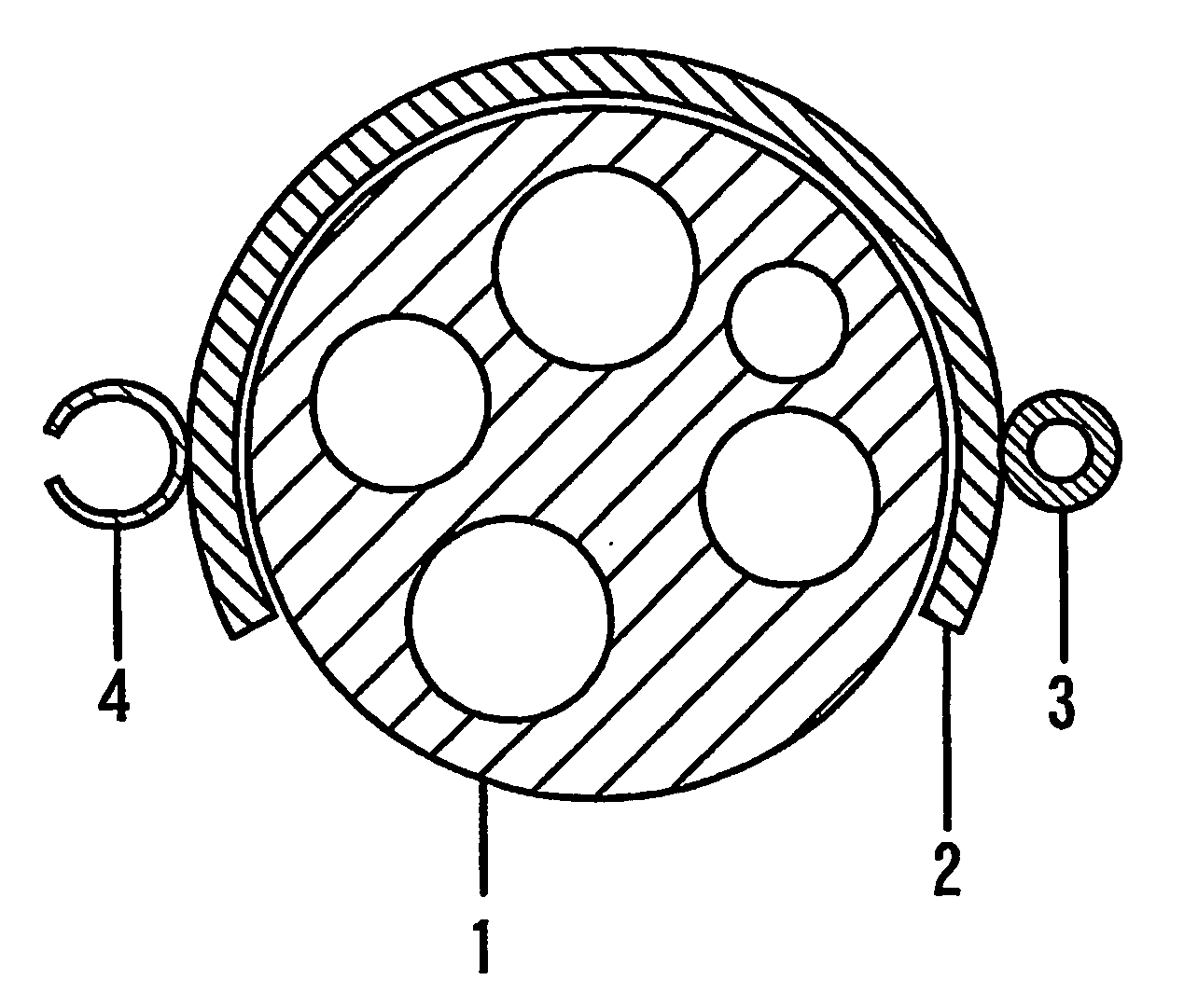
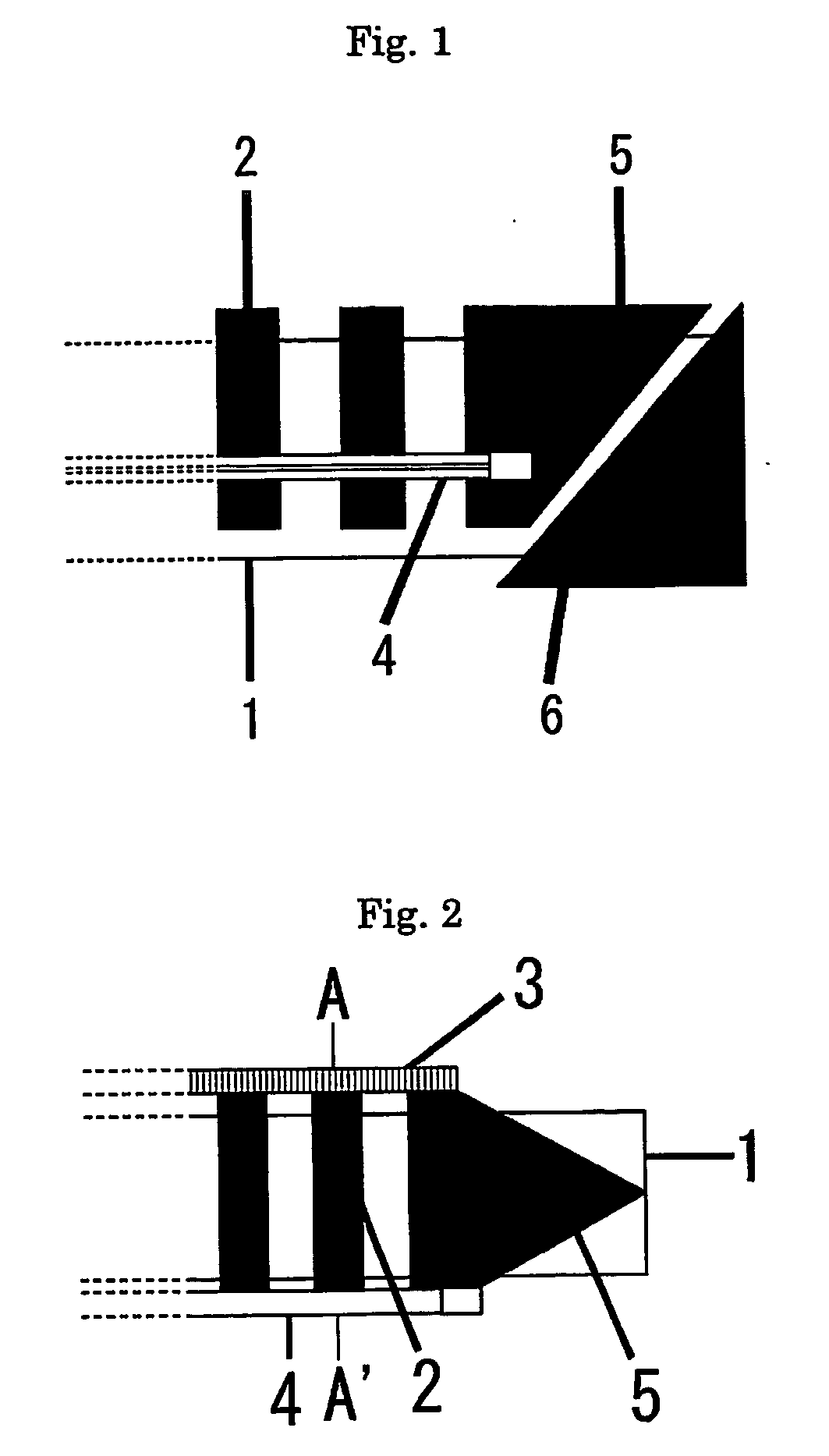
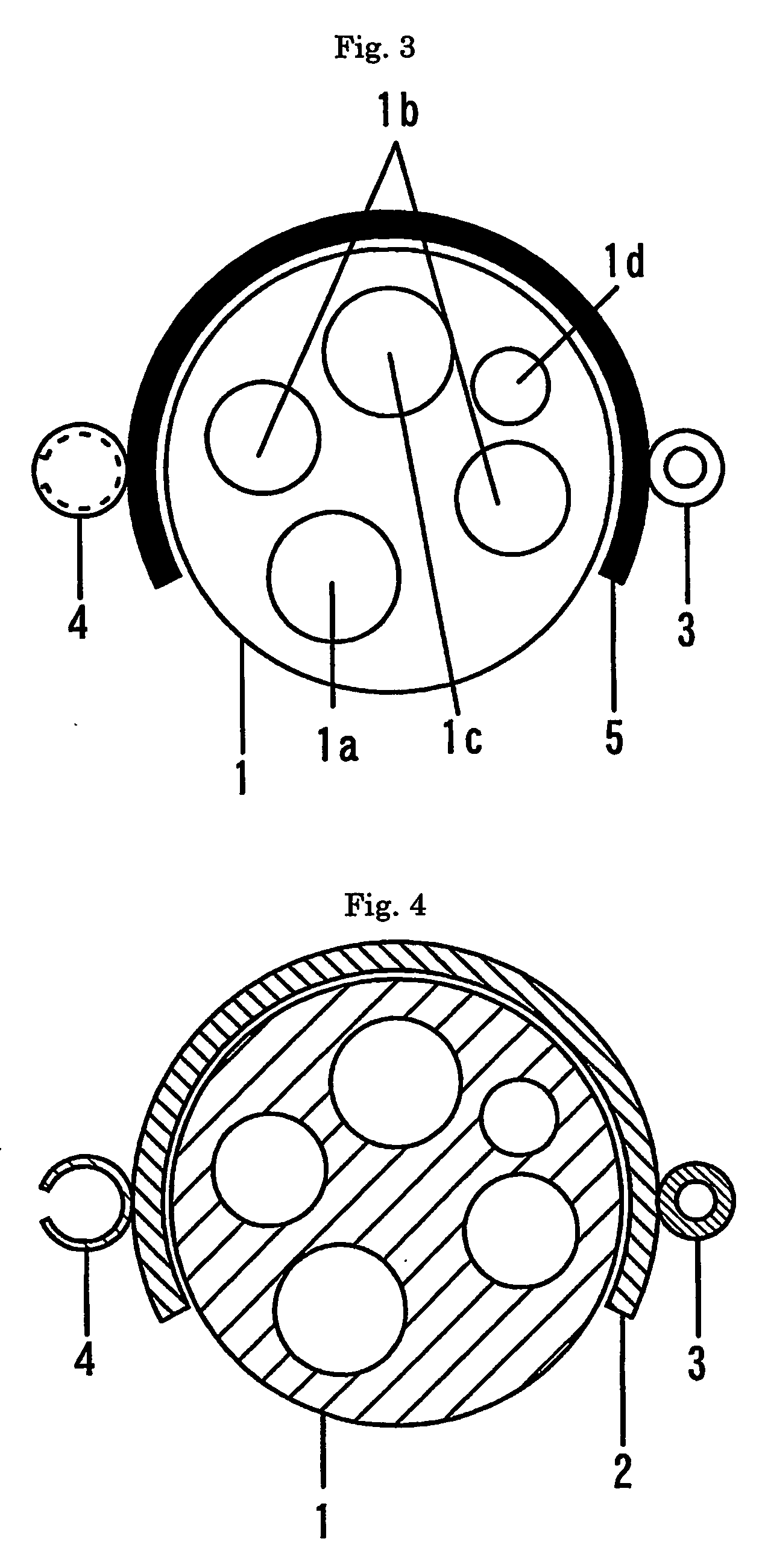
[0073] As an example of the present invention, description will be given of the external forceps channel device for an endoscope, to be provided on the outer periphery of the insertion portion of an existing endoscope, and of a use example thereof in a colon camera as an example of the endoscope.

Procedures for Use

[0074] Conditions of a case to which the use of the present invention is applicable include absence of high-degree adhesions after an operation or the like, and implementability under radioscopy.

[0075] The following works are performed as preparation prior to the implementation of the present invention.

[0076] A sufficient quantity of a lubricant is applied to the colon camera. To facilitate insertion of the colon camera and the external forceps channel device for an endoscope, a dilator or a slider is used as a device for dilating an anal region. When using the external forceps channel device for an endoscope to be annexed to an existing endoscope, the positioning cap ...


PUM


Abstract

The present invention was made in the light of the foregoing backgrounds, and an object thereof is to provide a forceps channel add-on device for an endoscope, provided on an outer periphery of an insertion portion of the endoscope. The forceps channel add-on device for an endoscope is an external forceps channel device for an endoscope, which is capable of providing two forceps channels or more without controlling the luminous intensity and the field of view of the endoscope, capable of extracting a substance larger than the bore diameter of the forceps channel multiple times while using the endoscope in a state of not being drawn out, without imposing a heavy burden on a patient, and also capable of performing examination after an operation as to whether complications are incurred after the evulsion, whether there is any other affected part overlooked, and so forth. An external forceps channel device for an endoscope, provided with an external forceps channel which is capable of being repeatedly inserted and extracted in a way of being guided by a guide provided on an endoscope separately and independently therefrom along an outside of an insertion portion of the endoscope while using the endoscope without drawing it out, the endoscope incorporating an air supply path, a light source, a CCD camera, and a forceps channel and including the insertion portion and an maneuvering portion, characterized in that provided is the external forceps channel capable of repeatedly extracting a foreign substance larger than a bore diameter of the incorporated forceps channel in a way of being guided by the guide along the outside of the endoscope, together with the whole external forceps channel itself in a state where the foreign substance is grasped by forceps inserted through the external forceps channel, and that provided is the external forceps channel capable of being repeatedly inserted in a way of being guided by the guide along the outside of the endoscope in a state where the endoscope is not drawn out.

Description

TECHNICAL FIELD [0001] The present invention relates to a forceps channel add-on device for an endoscope and, more particularly, to an external forceps channel device for providing a new forceps channel on an outer periphery of an insertion portion of an endoscope. BACKGROUND ART [0002] An existing endoscope normally has one forceps channel, and the forceps channel is not designed to allow the insertion of two pairs of forceps or more. Some endoscopes have two forceps channels. Moreover, among some endoscopes, there exist an endoscope provided with a forceps channel having a bore diameter larger than that of a normal forceps channel to increase the number of usable forceps types and is thereby capable of evulsion of a larger foreign substance; an endoscope provided with a forceps channel on the side to increase a degree of freedom of forceps; and the like. However, to install the forceps channel, the luminous intensity and the field of view of the endoscope had to be controlled. [00...

Claims


Application Information

Patent Timeline
Patent Type & Authority Applications(United States)
IPC IPC(8): A61B1/00G02B23/24A61B1/018A61B5/04
CPCA61B5/04A61B1/018A61B5/24
Inventor SHIMA, KIYOTERUKUMASAKA, HIDEO
Owner SHIMA KIYOTERU
Why Eureka
Eureka Blog
Learn More