
Image transfer material and heat transfer process using the same

a heat transfer process and image transfer technology, applied in the field of image transfer materials, can solve the problems of the cost involved in coating numerous solutions onto a support material and the overall feel of the imaged produ

Active Publication Date: 2007-07-26
SCHWENDIMANN JODI
View PDF45 Cites 46 Cited by
  • Summary
  • Abstract
  • Description
  • Claims
  • Application Information

AI Technical Summary

Benefits of technology

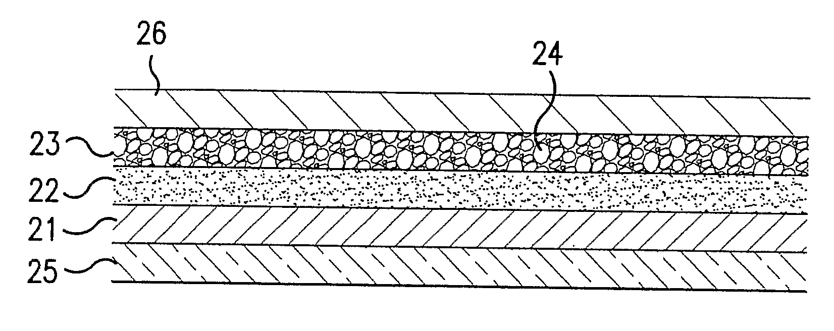
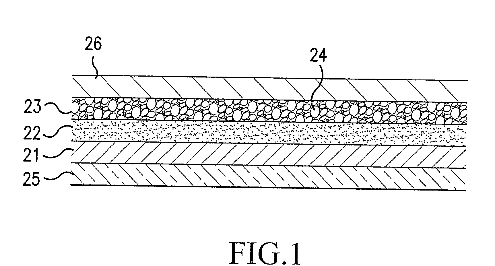
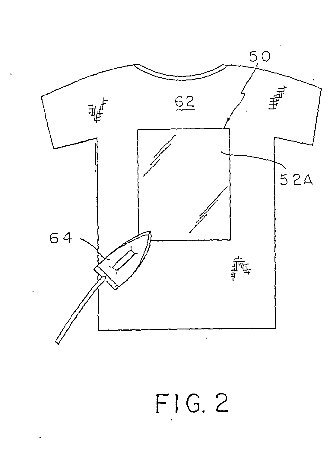
The present invention provides an improved transfer sheet for heat transfer of images to receptors. The transfer sheet includes a support sheet and a woven or non-woven web layer with an adhesion layer between them. The web layer is impregnated or coated with an image receiving formulation. The transfer sheet can be used to heat transfer the image to receptors by peeling off the web layer and adhesion layer from the support sheet and placing it on the receptor element. The adhesion layer melts and adheres the web layer to the receptor element, resulting in a durable image. The technical effect of this invention is to provide a more efficient and effective method for heat transfer of images to receptors.

Problems solved by technology

Problems with many known transfer sheets is the expense involved in coating numerous solutions onto a support material and the overall feel of the imaged product.

Method used


Image

  • Image transfer material and heat transfer process using the same
  • Image transfer material and heat transfer process using the same
  • Image transfer material and heat transfer process using the same

Examples


example 1

[0138] In one embodiment of the invention, the adhesion layer is an ethylene acrylic acid co-polymer. An example of this embodiment is Adhesion Layer Formulation 1:

Adhesion Layer Formulation 1ComponentsParts by weightEthylene Acrylic Acid86 parts Co-polymer Dispersion(Michem Prime 4983R, Michelman)Elastomeric emulsion5 parts(Hystretch V-29, BFGoodrich)Polyurethane Dispersion (Daotan4 partsVTW 1265, Vianova Resins)Polyethylene Glycol (Carbowax4 partsPolyethylene Glycol 400,Union Carbide)Polyethylene Glycol Mono1 part ((Tetramethylbutyl) Phenol)Ether (Triton X-100, Union Carbide)

[0139] Adhesion Layer Formulation 1, as an embodiment of the invention suitable for at least laser copiers and laser printers, is wax free. Adhesion Layer Formulation 1 may be prepared as follows: five parts of the elastomer dispersion are combined with eighty-six parts of an ethylene acrylic acid co-polymers dispersion by gentle stirring to avoid cavitation. Four parts of a polyurethane dispersion are then ...

example 2

[0140] This example relates to another adhesion layer formulation, Adhesion Layer Formulation 2.

Adhesion layer Formulation 2ComponentsPartsEthylene Acrylic Acid74 parts(weight)Co-polymers dispersion(Michem Prime 4938R, Michelman)Wax Dispersion (Michelman 73635M,25 parts(weight)Michelman)

[0141] Adhesion Layer Formulation 2 may be prepared in the following manner: the ethylene acrylic acid co-polymer dispersion and the wax dispersion are stirred (for example in a beaker with a stirring bar).

example 3

[0142] This example relates to another adhesion layer formulation, Adhesion Layer Formulation 3.

Adhesion Layer Formulation 3ComponentsPartsHeat-activated Polyurethane Dispersion100 Parts(Neorez R-551 (Avecia Co.)


PUM

PropertyMeasurementUnit
weightaaaaaaaaaa
weightaaaaaaaaaa
temperatureaaaaaaaaaa

Abstract

Provided is an image transfer material, comprising an optional support material, and a non-woven or woven fiber web layer, wherein the fiber web is impregnated or coated with a image receiving formulation. The fiber web layer is optionally attached to the support with an adhesion layer. Also provided is a heat transfer process wherein after imaging, the fiber web and adhesion layer are peeled from the optional support material and placed, preferably image side up (when imaged), on top of a receptor element. Alternatively, the fiber web and adhesion layer are peeled and then optionally imaged prior to being placed on the receptor element. Then, an optional non-stick sheet is placed over the imaged fiber web (if placed imaged side up) and heat is applied to the fiber web or the non-stick sheet, if present. The adhesion layer then melts and adheres the imaged web layer to the receptor element.

Description

BACKGROUND OF THE INVENTION [0001] 1. Field of the Invention [0002] The present invention relates to an image transfer material, comprising a support material, and a non-woven or woven fiber web layer, wherein the fiber web is impregnated or coated with materials that constitute an image receiving formulation. The fiber web layer is attached to the support by an adhesion layer. The top surface of the fiber web is receptive to images, for instance, ink jet images, photocopy images, etc. Optionally, one or more opaque layers may be coated between the adhesion layer and the fiber web. The optional opaque layer(s) adds a rigid or stiff quality to the transfer material for ease of handling, as well as having opacity, especially white, to enhance visibility of the image when placed thereon. [0003] The present invention further relates to a heat transfer process using the same material. For instance, after imaging, the fiber web and adhesion layer are peeled away from the support material ...

Claims


Application Information

Patent Timeline
Patent Type & Authority Applications(United States)
IPC IPC(8): B41M5/40B41M5/035B41M5/52B44C1/17D06Q1/00
CPCB41M5/035B41M5/0355B41M5/52B44C1/1712Y10T428/2852D06Q1/00Y10T428/1362Y10T428/2817D06P5/003
Inventor WILLIAMS, SCOTT A.
Owner SCHWENDIMANN JODI
Learn More