
Modular pressure support system

a support system and module technology, applied in the field of gas flow delivery system, can solve the problems of inhibiting one or more functionalities of the respiratory device, complicated and/or inconvenient to couple and/or uncouple and inconvenient use of the conventional interface between the humidifier and the respiratory devi

Active Publication Date: 2007-07-26
PHILIPS RS NORTH AMERICA LLC
View PDF6 Cites 243 Cited by
  • Summary
  • Abstract
  • Description
  • Claims
  • Application Information

AI Technical Summary

Benefits of technology

[0011] Another aspect of the invention relates to a pressure support system that comprises a gas flow generating system, a tank, a patient circuit, a conduit, and a barrier. The gas flow generating system generates a pressurized flow of breathable gas. The tank enables the pressurized flow of breathable gas to pass therethrough, and is adapted to contain a liquid such that a humidity level of the pressurized flow of breathable gas is elevated as the pressurized flow of breathable gas passes therethrough. The patient circuit delivers the pressurized flow of breathable gas to a patient. The conduit is connected at one end to an outlet of the gas flow generating system and at the other end to an inlet of the tank so as to communicate the pressurized flow of breathable gas from the gas flow generating system to the tank. The barrier is formed within the conduit, and inhibits the liquid contained by the tank from ingressing on the gas flow generating system when the liquid is introduced into the conduit.

Problems solved by technology

However, conventional interfaces between a humidifier and a respiratory device are often inconvenient to use.
In addition, it is often complicated and / or inconvenient to couple and / or uncouple the humidifier to the respiratory device.
Additionally, coupling the humidifier to the respiratory device may inhibit one or more functionalities of the respiratory device.
For example, in some instances, the pressure of the gas being delivered to the patient may not be measured accurately when a humidifier is installed.
Further, conventional systems may not provide suitable safeguards against fluid that is stored within the humidifier from being spilled into the respiratory device.

Method used


Image

  • Modular pressure support system
  • Modular pressure support system
  • Modular pressure support system

Examples


Embodiment Construction

)

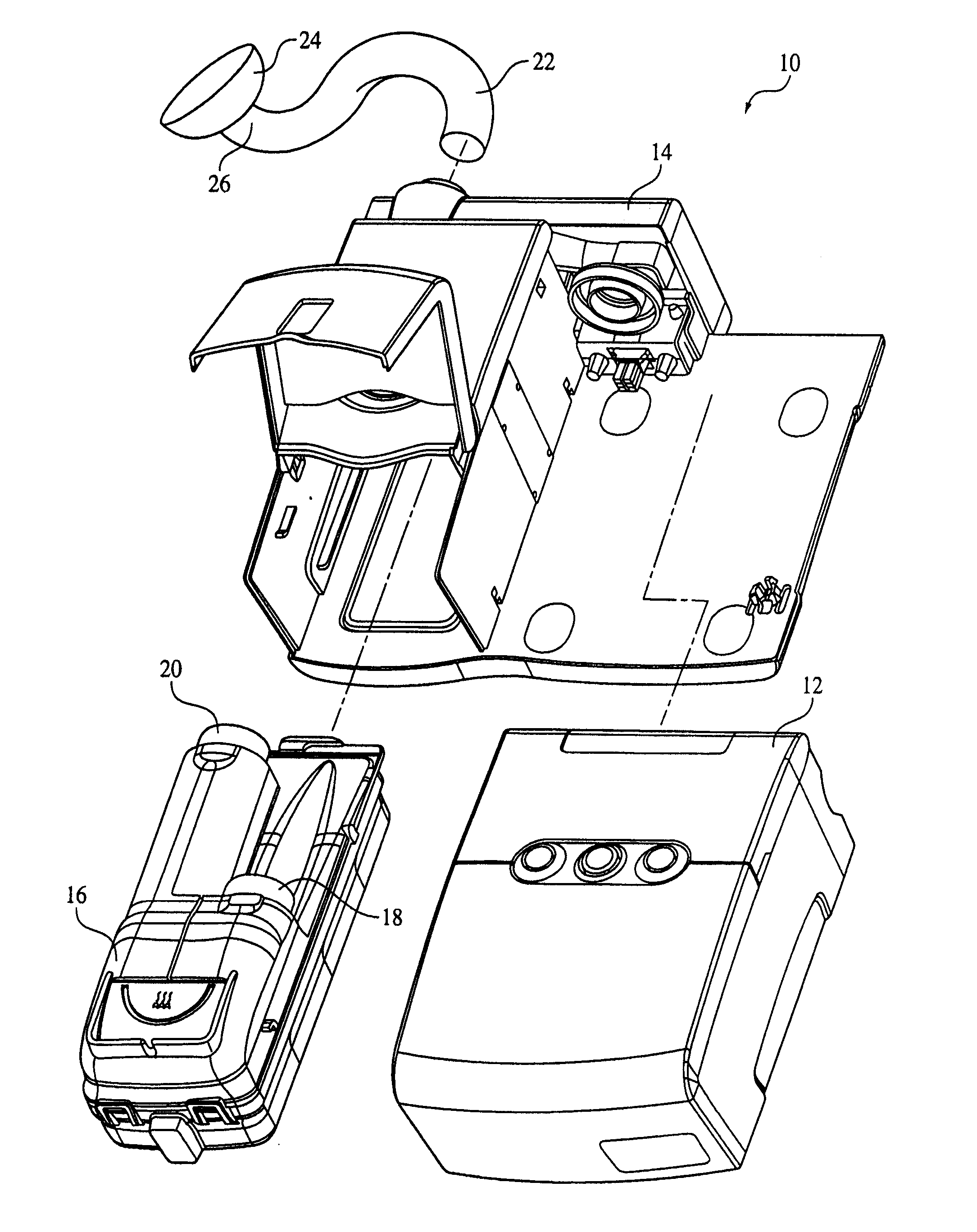
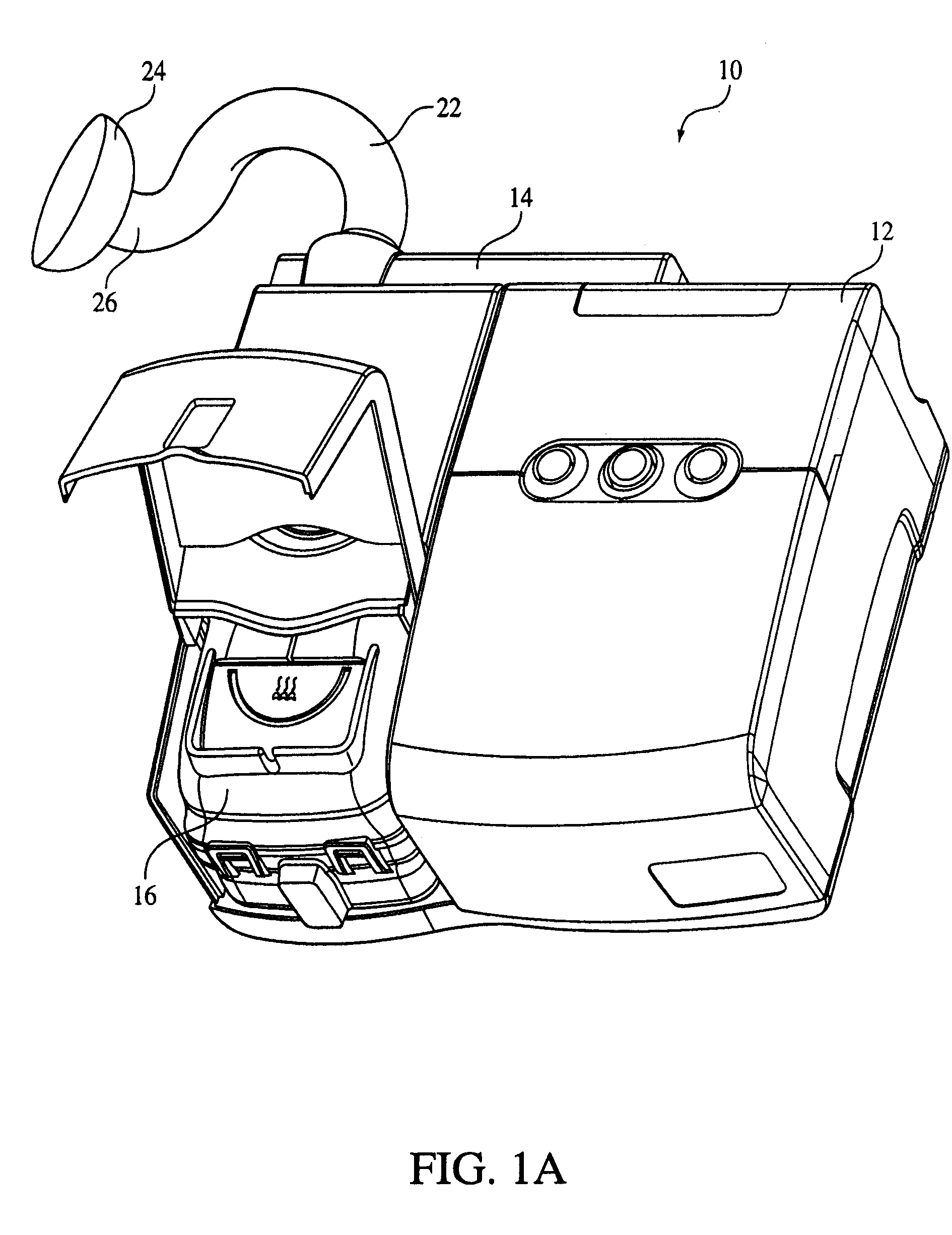
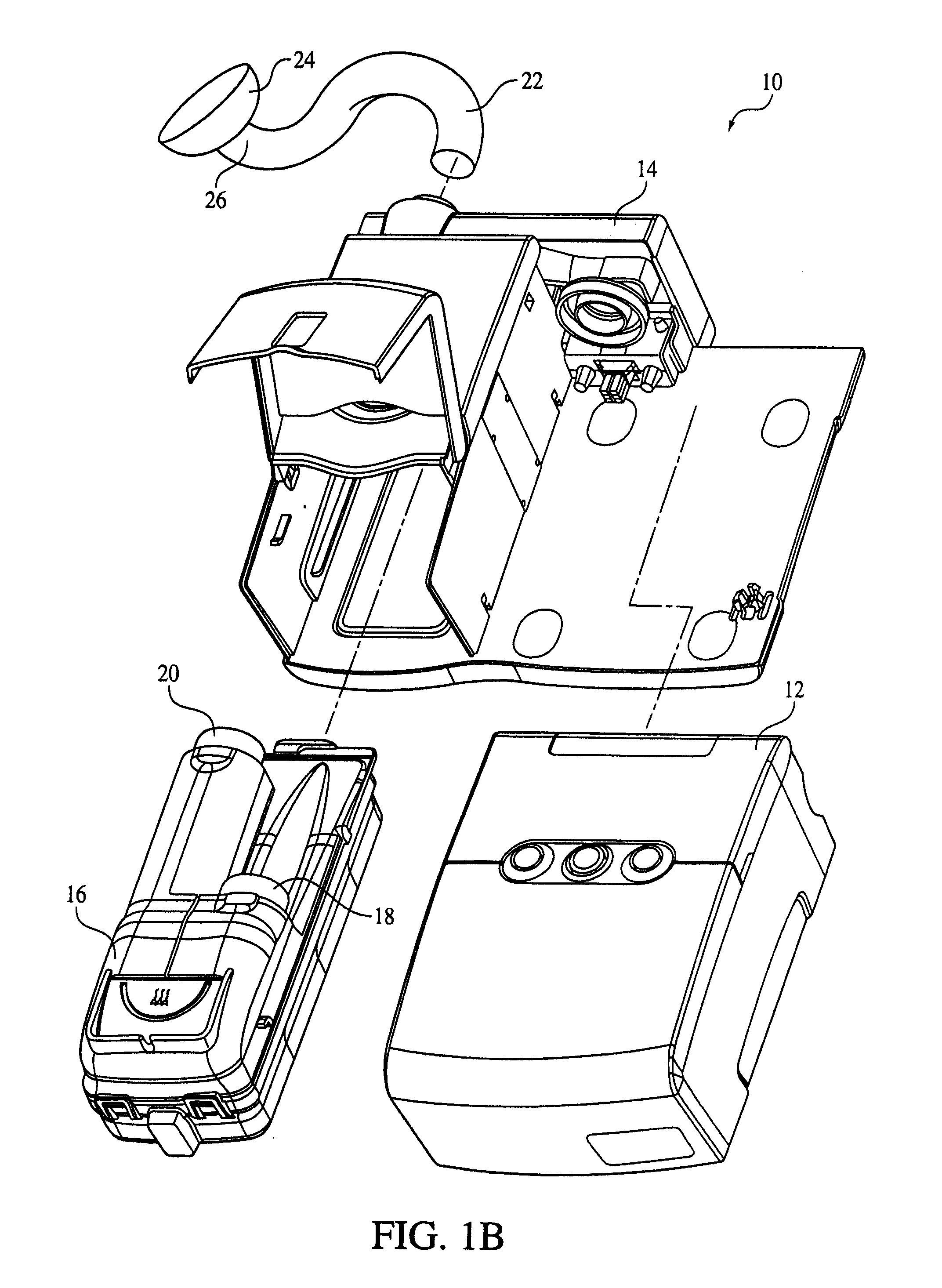
[0037]FIGS. 1A and 1B illustrate a pressure support system 10 that provides a pressurized flow of breathable gas to a patient, according to one embodiment of the invention. Pressure support system 10 includes a gas flow generating system 12 that generates the pressurized flow of breathable gas according to a predetermined mode of ventilation. Gas flow generating system 12 is any device that generates a flow of gas for delivery to the airway of a patient. Gas flow generating system 12 may, for example, take the form of a ventilator (invasive, non-invasive, or both), an anesthesia machine, a continuous positive airway pressure (CPAP) device that delivers a flow of gas at a constant pressure, or a variable pressure device that delivers a flow of gas to the patient such that pressure or rate of flow varies. Examples of variable pressure devices include an auto-titrating device that delivers a flow of gas whose pressure varies with the monitored condition of the patient, a proportional ...


PUM


Abstract

A pressure support system that comprises a patient circuit, a docking assembly, and a tank. The patient circuit delivers a pressurized flow of breathable gas to a patient. The docking assembly has an inlet and an outlet that is adapted to receive the pressurized flow of breathable gas, and is also adapted to be connected with the patient circuit. The tank is constructed and arranged to be removably connected with the docking assembly, and enables the pressurized flow of breathable gas to pass therethrough. The tank is also adapted to contain a liquid such that a humidity level of the pressurized flow of breathable gas is elevated as the pressurized flow of breathable gas passes therethrough.

Description

BACKGROUND OF THE INVENTION [0001] 1. Field of the Invention [0002] The invention pertains to a gas flow delivery system that provides a pressurized flow of breathable gas to a patient, and, in particular, to as gas flow delivery system with an optional modular humidification system, and universal interface port. [0003] 2. Description of the Related Art [0004] Ventilators, pressure support systems, and other respiratory devices that provide a pressurized flow of breathable gas to a patient are known. In some instances, a humidifier may be added to a respiratory device to elevate a humidity level of the gas delivered to the patient. However, conventional interfaces between a humidifier and a respiratory device are often inconvenient to use. In addition, it is often complicated and / or inconvenient to couple and / or uncouple the humidifier to the respiratory device. [0005] Additionally, coupling the humidifier to the respiratory device may inhibit one or more functionalities of the resp...

Claims


Application Information

Patent Timeline
IPC IPC(8): A61M11/00
CPCA61M16/0051A61M16/109A61M2016/0027A61M2016/0039A61M2205/123A61M2205/3355A61M2205/3553A61M2205/3584A61M2205/42A62B7/02A61M16/0057A61M16/04A61M16/06A61M16/0875A61M16/0069A61M16/107A61M16/16A61M16/161A61M2205/505A61M16/024A61M2209/086A61M16/0003
Inventor KEPLER, JEFFREYMORT, MICHAEL E.SEMAN, RICHARD A. JR.DIMATTEO, MARKMCCRACKEN, CHRISTOPHER J.VREELAND, JAMES S.RADNEY, STEVEN B.BOBECK, MICHAELCAMERON, ALLANCHASTAIN, DAVID P.MCDERMOTT, PATRICK F.PALM, WILLIAM J.THOMPSON, ROY A.
Owner PHILIPS RS NORTH AMERICA LLC
Learn More