
Method and apparatus for soft-error immune and self-correcting latches

a technology of self-correction and latches, applied in error detection/correction, instruments, computing, etc., can solve problems such as value upset, system restart, and reduced latch designs, but not eliminated, and solved problems such as upsets

Inactive Publication Date: 2007-07-19
INT BUSINESS MASCH CORP
View PDF24 Cites 29 Cited by
  • Summary
  • Abstract
  • Description
  • Claims
  • Application Information

AI Technical Summary

Benefits of technology

[0011] It is therefore one object of the present invention to provide an area efficient design for a self-correcting latch.
[0012] It is another object of the present invention to provide such a latch design that can handle multiple upsets over time.
[0014] The foregoing objects are achieved in a method of storing a scanned value by loading the value into at least three latches stages, generating an output value based on a majority of the latch stage outputs, and feeding the output value back to the inputs of the latches to reload the latch stages with the output value. This refreshing of the latches repairs any upset latch stage and restores the latch circuit to its original (scanned) state. The latch circuit may be repeatedly refreshed, preferably on a periodic basis, to prevent failures arising from multiple upsets. In one implementation, the feedback path includes a front-end multiplexer having one input which receives the scan-in line and another input which receives the output of the majority gate. Control logic for the multiplexer selects the output value to pass to the latch stages during the refresh phase. The exemplary embodiment arranges the latch stages in a master-slave configuration with a check stage at the slave level. The master stage (controlled by a first clock signal) stores the value during a first clock half-cycle, and passes the value to the slave and check stages (controlled by a second clock signal) during the next clock half-cycle. The method is particularly suited for bits set at power-on which control of a microprocessor over its entire power-on hours.

Problems solved by technology

However, these values can be upset during microprocessor operation, e.g., from stray radiation or electrostatic discharge.
This upset is correctable by scanning a new value, but the system may only allow scanning at power-on, meaning that the system must be restarted if a clock control latch becomes incorrectly set.
These latch designs reduce, but do not eliminate, the problem of upsets.
As a related issue, full redundancy in latch designs may be too costly in terms of physical size (chip area), speed, and power consumption.

Method used


Image

  • Method and apparatus for soft-error immune and self-correcting latches
  • Method and apparatus for soft-error immune and self-correcting latches
  • Method and apparatus for soft-error immune and self-correcting latches

Examples


Embodiment Construction

)

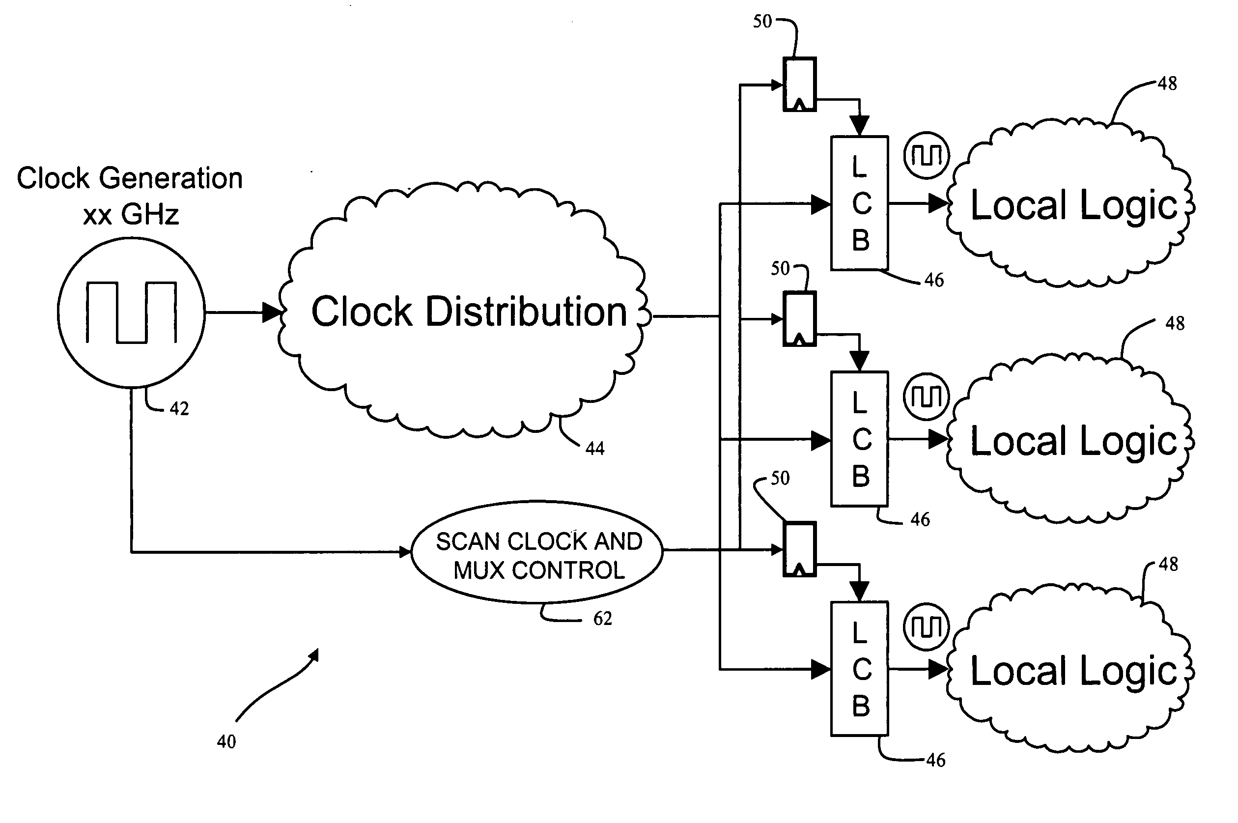
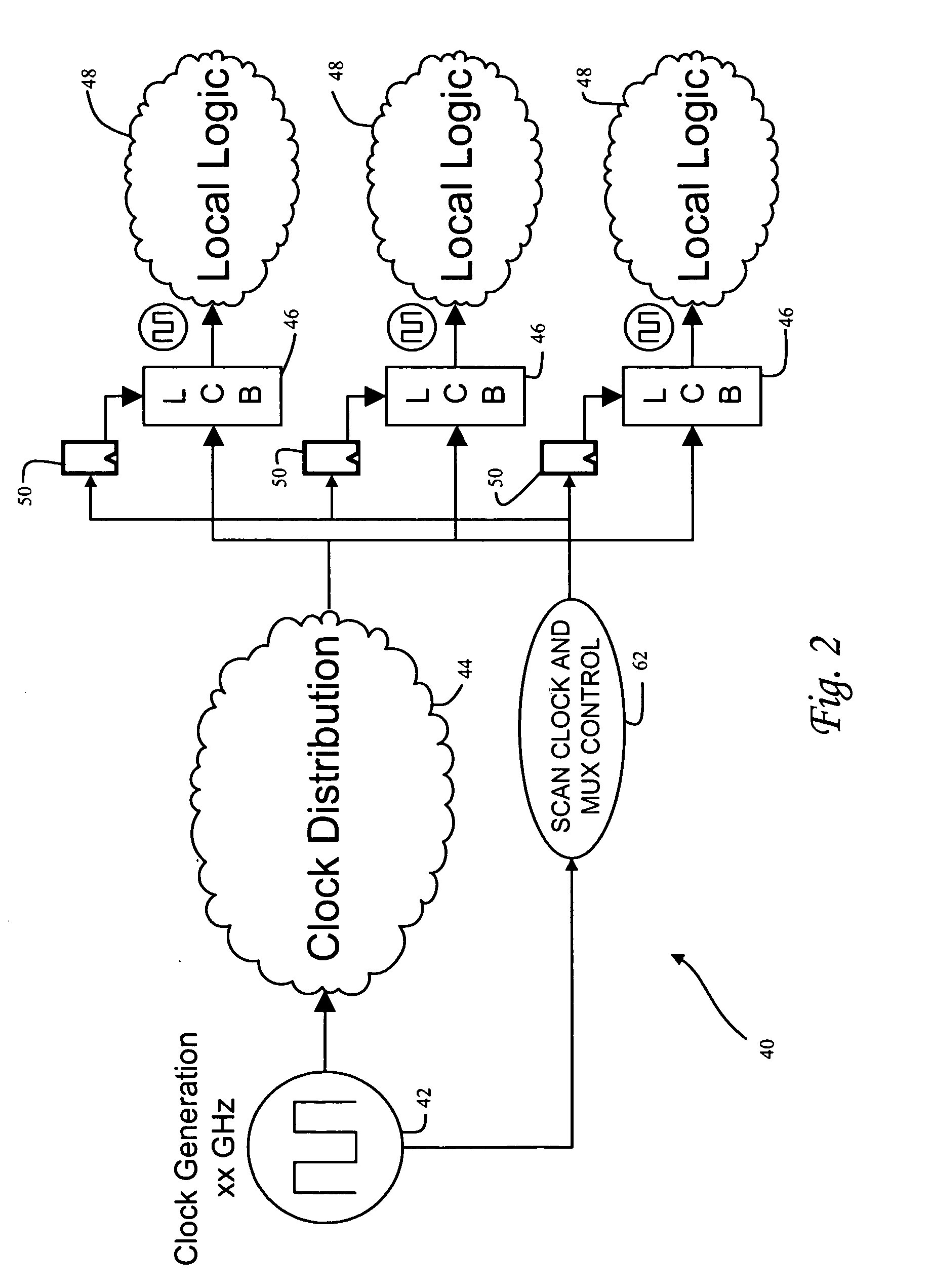
[0023] With reference now to the figures, and in particular with reference to FIG. 2, there is depicted one embodiment 40 of a clock control system which utilizes a novel latch circuit constructed in accordance with the present invention. Clock control system 40 is adapted for use within an integrated circuit such as a microprocessor. While clock control system 40 provides one example of how the invention may be implemented, those skilled in the art will appreciate that the invention is not so limited, and may be used in other latch control systems of a microprocessor besides clock control systems.

[0024] Clock control system 40 is generally comprised of a clock generation circuit 42, a clock distribution network 44, and a plurality of local clock buffers (LCBs) 46. Clock generation circuit 42 includes a phase-lock loop to create a master clock signal. The master clock signal is fed to the clock distribution network to render synchronized global clock signals at LCBs 46. Each LCB 4...


PUM


Abstract

A scanned value is stored by loading the value into at least three latch stages, generating an output value based on a majority of the latch stage outputs, and feeding the output value back to the inputs of the latch stages to reload the latch stages with the latch circuit output value. Refreshing of the latch stages in this manner repairs any upset latch stage and restores the latch circuit to its original scanned state. The latch circuit may be repeatedly refreshed, preferably on a periodic basis, to prevent failures arising from multiple upsets. The feedback path may include a front-end multiplexer which receives the scan-in line and the output of the majority gate. Control logic selects the output value from the majority gate to pass to the latch stages during the refresh phase. The latch stages may be arranged in a master-slave configuration with a check stage at the slave level. The method is particularly suited for self-correcting scan latches of a microprocessor control system.

Description

BACKGROUND OF THE INVENTION [0001] 1. Field of the Invention [0002] The present invention generally relates to computer systems, specifically to a method of storing values in latches of a computer system, and more particularly latches which store state information for extended periods of time. [0003] 2. Description of the Related Art [0004] The basic structure of a conventional processing unit 10 for a computer system is shown in FIG. 1. In this example processing unit 10 is a dual-core processor having two processor cores 12a and 12b which carry out program instructions in order to operate the computer. Processing unit 10 also includes a memory subsystem 14, a scan controller 16, and a JTAG interface 18. The computer system may be a symmetric multi-processor (SMP) computer which uses a plurality of processing units 10 that are generally identical, that is, they all use a common set or subset of instructions and protocols to operate, and generally have the same architecture. An exem...

Claims


Application Information

Patent Timeline
Patent Type & Authority Applications(United States)
IPC IPC(8): G01R31/28
CPCG06F11/1666G06F11/267G06F11/187G06F11/183
Inventor DRAKE, ALAN J.OSOWSKI, AJ KLEINMARTIN, ANDREW K.
Owner INT BUSINESS MASCH CORP
Learn More