
Method and system for powering a device using a data communications signal line

a data communication signal and power supply technology, applied in data switching networks, instruments, data switching details, etc., can solve the problems of not providing powering devices coupled to the interface, adding outlets to power peripheral devices such as radios, and increasing installation costs and time requirements, so as to achieve powerless state of high impedan

Active Publication Date: 2007-07-19
SENSORMATIC ELECTRONICS CORP
View PDF9 Cites 14 Cited by
  • Summary
  • Abstract
  • Description
  • Claims
  • Application Information

AI Technical Summary

Benefits of technology

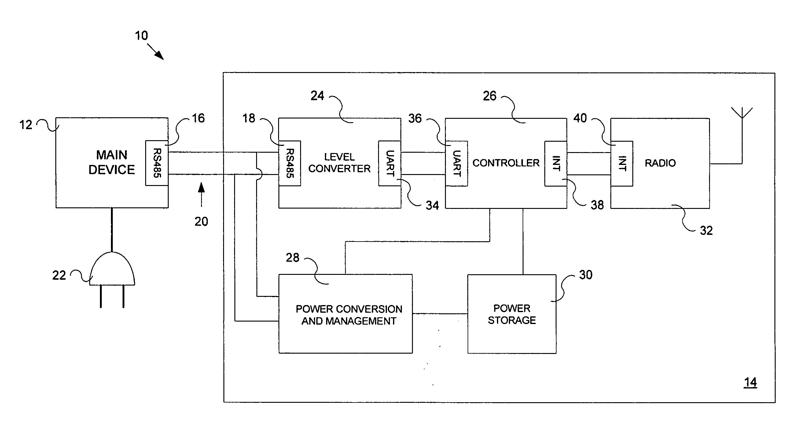
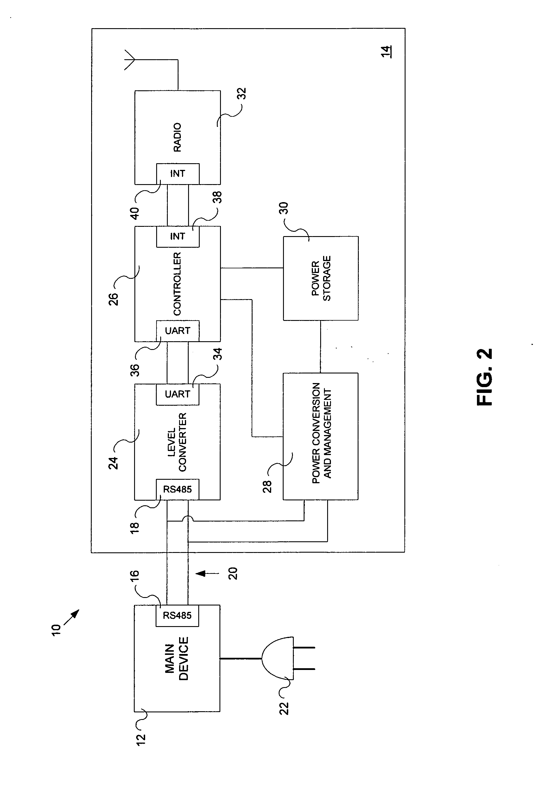
[0011] According to one aspect, the present invention provides a system for transferring power using a data communications signal line. The data communications signal line is in a high impedance powerless state when idle. A main device is electrically coupled to the data communications signal line. The main device generates and transmits a signal on the data communications signal line. The signal includes power generation and non-power generation characters. A peripheral device is electrically coupled to the data communications signal line. The peripheral device has a functional unit arranged to perform a desired function for the peripheral device. A power conversion module is electrically coupled to the data communications signal line and receives the signal. The power conversion module converts power from the received signal to a form suitable for storage. A controller is in electrical communication with the functional unit and the power conversion module. The controller receives the power generation and non-power generation characters, strips the power generation characters from the signal and transmits the non-power generation characters to the functional unit.
[0012] According to another aspect, the present invention provides a method for receiving power from a data communications signal line in which the data communications signal lin...

Problems solved by technology

In addition, it is also possible that existing installations that are to be retrofitted to allow remote communication using devices such as radios do not include additional power outlets, or make other provisions for providing external power.
Even for new installations, adding outlets to power peripheral devices such as radios adds to the cost of installation as well as the time needed to install the outlets or otherwise run power to installation location.
Many types of serial interfaces, such as RS-485 and RS-422 interfaces, do not provide for powering devices coupled to the interface.
As such, power can not be provided to a connected peripheral device via the serial interface and, as noted above, the remote device must be powered by running a separate power line from another source, using a battery, etc.

Method used


Image

  • Method and system for powering a device using a data communications signal line
  • Method and system for powering a device using a data communications signal line
  • Method and system for powering a device using a data communications signal line

Examples


Embodiment Construction

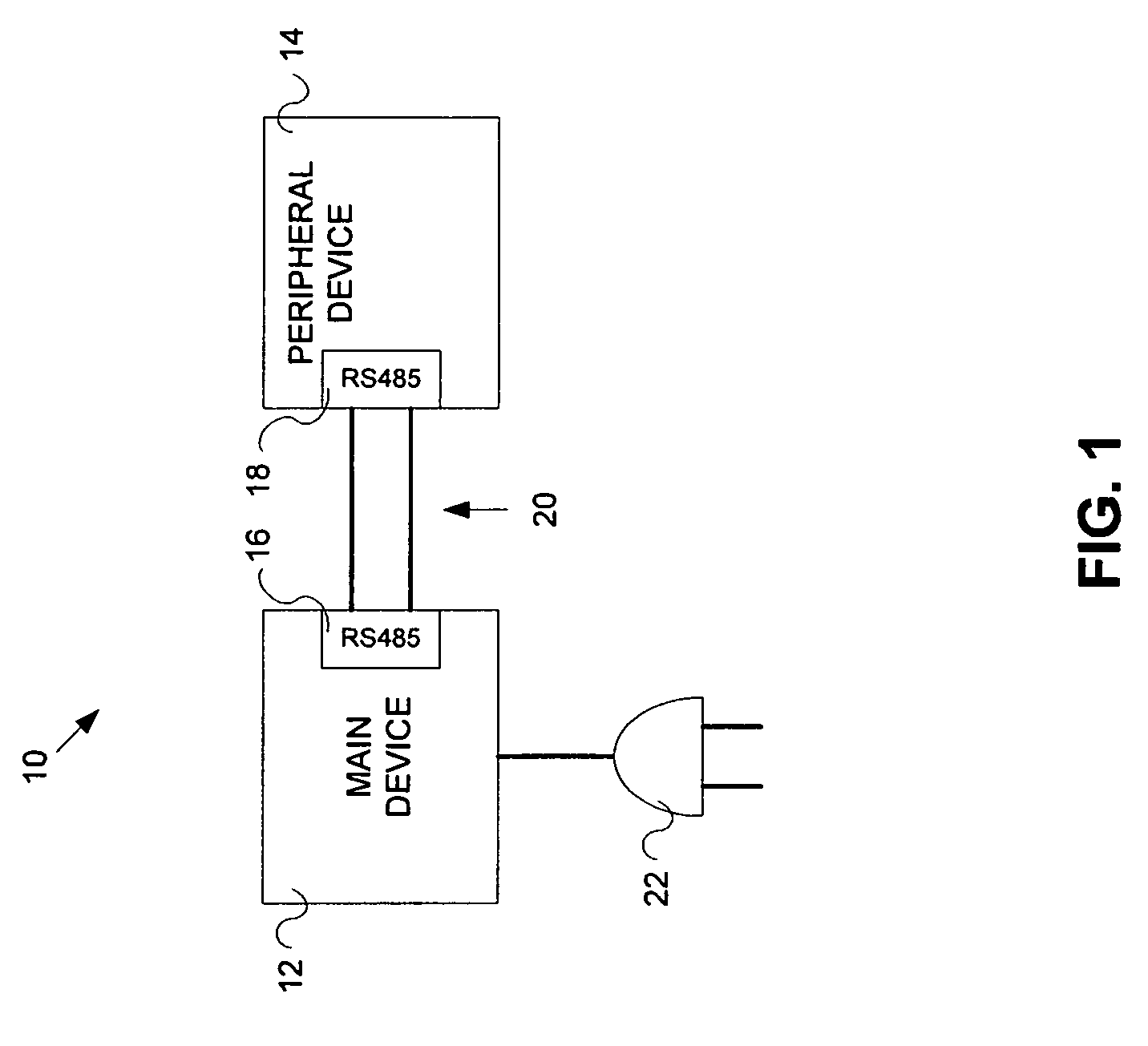
[0020] The present invention advantageously provides a system that allows a peripheral device to receive power from a serial communications line whose protocol does not typically allow for the transmission of power from the main device to the peripheral device. Referring now to the drawing figures in which like reference designators refer to like elements there is shown in FIG. 1 a system constructed in accordance with the principles of the present invention and designated generally as “10.” System 10 includes main device 12 and peripheral device 14, each having a serial interface 16 and 18, respectively, that are electrically interconnected via serial communications line 20. Of note, although the present invention is described with reference to serial interfaces 16 and 18, and in particular serial interfaces using the RS-485 protocol, the invention is not limited to such and the ensuing description is offered for ease of understanding. It is contemplated that the present invention ...


PUM


Abstract

A system and method for transferring power using a data communications signal line. The data communications signal line is in a high impedance powerless state when idle. A main device is electrically coupled to the data communications signal line. The main device generates and transmits a signal on the data communications signal line. The signal includes power generation and non-power generation characters. A peripheral device is electrically coupled to the data communications signal line. The peripheral device has a functional unit arranged to perform a desired function for the peripheral device. A power conversion module is electrically coupled to the data communications signal line and receives the signal. The power conversion module converts power from the received signal to a form suitable for storage. A controller is in electrical communication with the functional unit and the power conversion module. The controller receives the power generation and non-power generation characters, strips the power generation characters from the signal and transmits the non-power generation characters to the functional unit.

Description

CROSS-REFERENCE TO RELATED APPLICATIONS [0001] n / a STATEMENT REGARDING FEDERALLY SPONSORED RESEARCH OR DEVELOPMENT [0002] n / a BACKGROUND OF THE INVENTION [0003] 1. Statement of the Technical Field [0004] The present invention relates to providing power to peripheral devices, and more particularly to providing power to a device such as a wireless transmitter using a data communications signal line that is not always active. [0005] 2. Description of the Related Art [0006] While new devices and buses such as the Universal Serial Bus (“USB”) include provisions for providing power to remotely connected peripheral devices, there is a very large body of technologies and deployed equipment that provide interfaces for serial communication to remote devices that do not include provisions for providing power. Many serial interface technologies, such as RS-485 and RS-422 interfaces, were historically used for programming or configuration access by service personnel, or hard wired to centralized...

Claims


Application Information

Patent Timeline
IPC IPC(8): G06F13/20
CPCH04L12/10H04L2012/4026H04L12/403H04L12/40045G06F1/266
Inventor HALL, STEWART E.COOK, JAMES A.
Owner SENSORMATIC ELECTRONICS CORP
Learn More