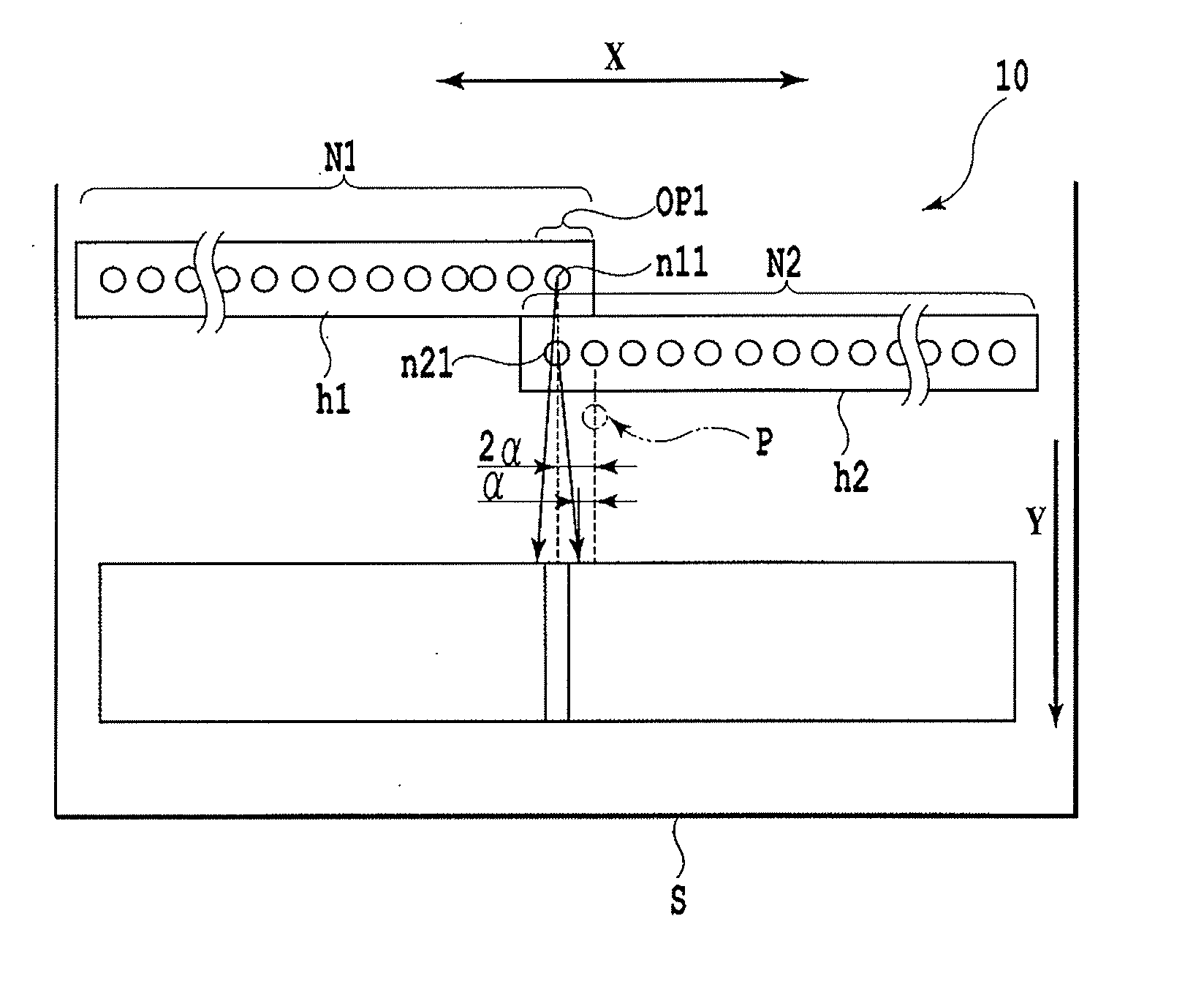
Apparatus and method for ink jet printing
a technology of ink jet printing and nozzles, applied in the direction of printing, inking apparatus, other printing apparatus, etc., can solve the problems of uneven density of formed images, degrade image quality, and difficult to densely arrange a large number of nozzles in a single substrate in a line, so as to reduce density unevenness
- Summary
- Abstract
- Description
- Claims
- Application Information
AI Technical Summary
Benefits of technology
Problems solved by technology
Method used
Image
Examples
first embodiment
[0048] First, with reference to FIGS. 13 and 14, description will be given of an example of basic configuration of an ink jet printing apparatus applied to the embodiment of the present invention.
[0049]FIG. 13 is a perspective view schematically showing an example of configuration of a mechanism section of a full line type ink jet printing apparatus applied to the embodiment of the present invention.
[0050] The full line type ink jet printing apparatus 60 in the present example prints an image on a print sheet S as a print medium by ejecting ink from nozzles in a print head 10 provided at a given position while conveying the print sheet S on a conveying belt 61. The long print head 10 extends over a width larger than that of print sheets S of an applicable maximum size. The print head 10 enables an image to be continuously printed by ejecting ink droplets onto the print sheet S being continuously conveyed. In the present example, the print head 10 includes a print head 10Y that eje...
second embodiment
[0079] Now, a second embodiment of the present invention will be described.
[0080] With ink jet printing apparatuses, ink droplets land on the print sheet S land on a rectangular enclosed pixel area virtually set on the print sheet S. At this time, the ink droplets landed on the print medium bleed and protrude from pixel area to form round dots. In this case, at a lower print duty, a smaller number of dots are placed on the print sheet S, allowing the optical density to be easily increased. However, at a higher print duty, adjacent dots overlap each other, suppressing an increase in optical density. To correct this, the gamma correction process is normally executed for the density value expressed by the original image data so as to reduce the density value of an image formed on the print sheet S. The second embodiment executes an integrated correction composed of this gamma correction integrated with the end deviation correction (see FIG. 6B).
[0081] Thus, compared to the end deviat...
third embodiment
[0083] Now, a third embodiment of the present embodiment will be described with reference to FIGS. 7 and 8.
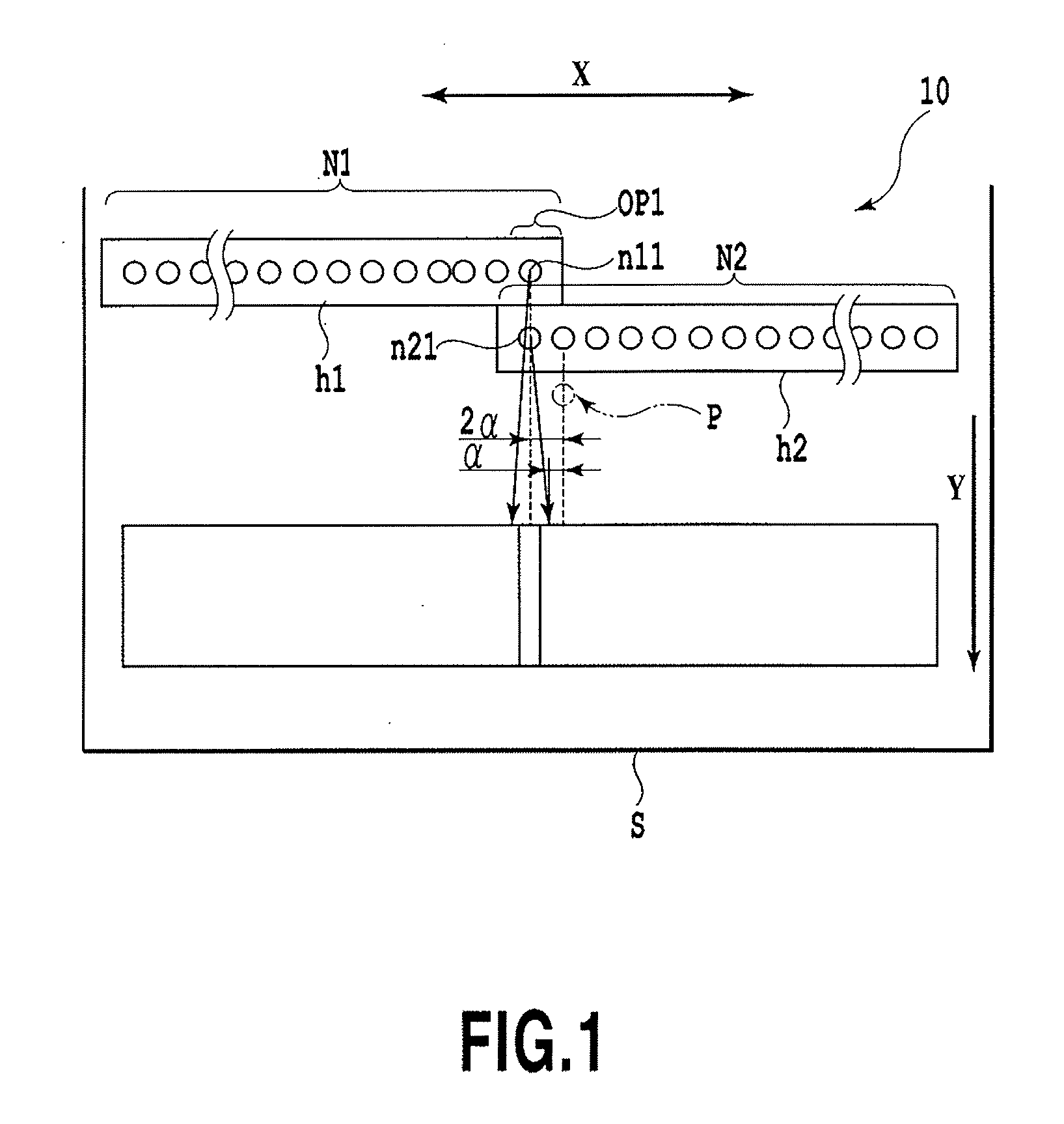
[0084] In the description of the example for the first and second embodiments, the total distance (2α) corresponding to the maximum end deviation amounts of the terminal nozzles in the head chips h1 and h2 is equal to the distance between the terminal nozzle n21 in the head chip h2 and the reference position P. In contrast, in the print head 10 according to the third embodiment, as shown in FIG. 7, the head chip h2 is placed so that the distance T between the terminal nozzle n21 in the head chip h2 and the reference position P is more than double the maximum end deviation amount (α). In FIG. 7, OP2 denotes the connecting portion between the head chips h1 and h2.
[0085] This makes it possible to suppress a rapid change in the density of an image formed by the connecting portion OP2. Thus, an image formed by the connecting portion OP2 and images formed by other portions can be s...
PUM
 Abstract
Description
Claims
Application Information
 - R&D
- Intellectual Property
- Life Sciences
- Materials
- Tech Scout
- Unparalleled Data Quality
- Higher Quality Content
- 60% Fewer Hallucinations
Browse by: Latest US Patents, China's latest patents, Technical Efficacy Thesaurus, Application Domain, Technology Topic, Popular Technical Reports.
© 2025 PatSnap. All rights reserved.Legal|Privacy policy|Modern Slavery Act Transparency Statement|Sitemap|About US| Contact US: help@patsnap.com


