
Contactless card and contactless card system

a technology of contactless card and contactless card, which is applied in the field of contactless smart cards, can solve the problems of degrading the identification rate of magnetic or barcode identification systems, and achieve the effect of preventing circuit defects and communication errors

Inactive Publication Date: 2007-07-19
SAMSUNG ELECTRONICS CO LTD
View PDF8 Cites 49 Cited by
  • Summary
  • Abstract
  • Description
  • Claims
  • Application Information

AI Technical Summary

Benefits of technology

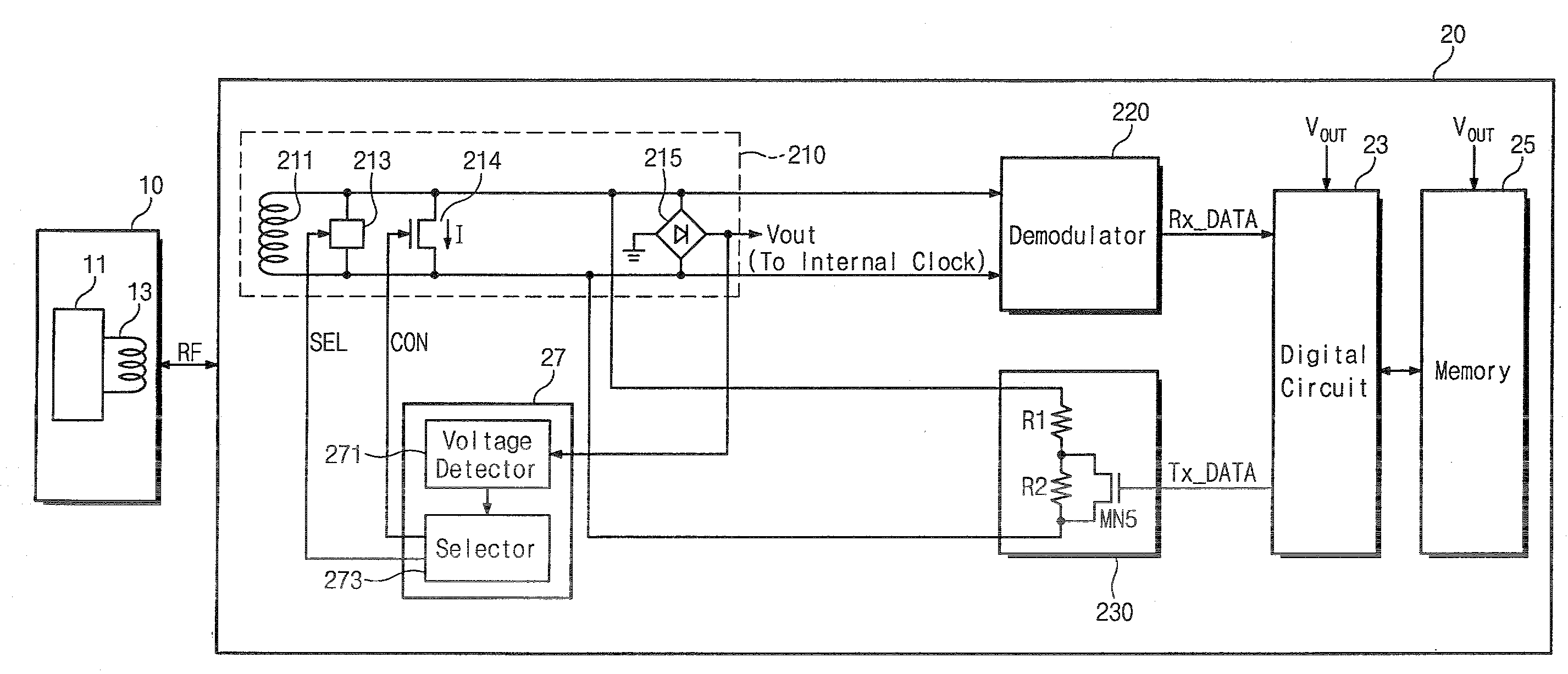
[0010]Exemplary embodiments of the present invention are directed to a contactless identification device and a system capable of preventing circuit defects and communication errors due to an excessive voltage transferred to a smart card or tag during a proximity operation mode.

Problems solved by technology

Such magnetic or barcode identification systems have a problem of degrading a rate of identification over time due to weakening magnetic force, physical damages, or other destructions.
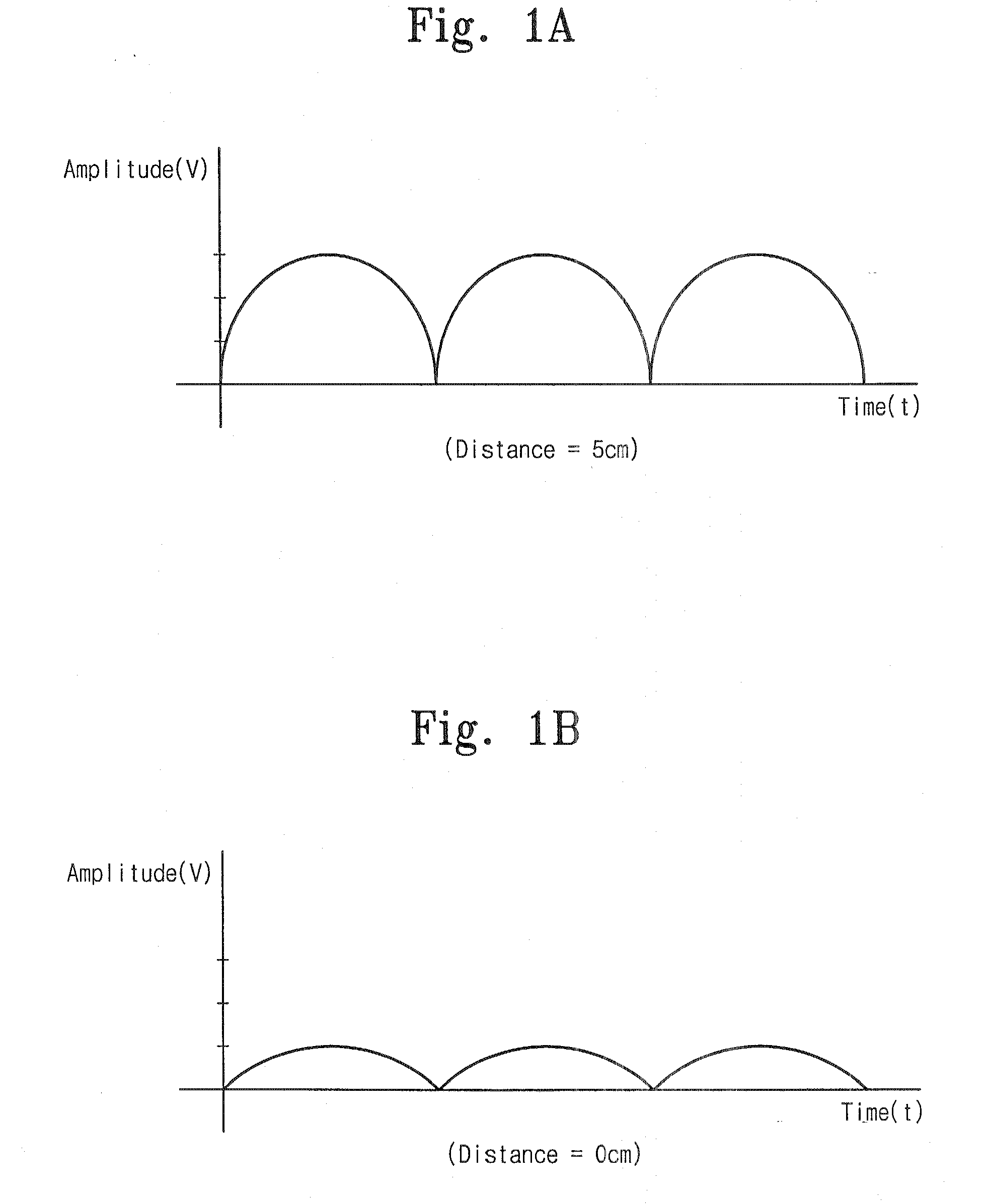
Since such an excessive voltage causes damage to a central processor unit or IC chip in the smart card, a technique to block the excessive voltage that is generated during the proximity mode is required.
As a result, the intensity of the data signal transferred into an internal demodulator of the card reader becomes lower so as to cause communication errors thereby.

Method used


Image

  • Contactless card and contactless card system
  • Contactless card and contactless card system
  • Contactless card and contactless card system

Examples


Embodiment Construction

[0028]Exemplary embodiments of the present invention will be described below in more detail with reference to the accompanying drawings. The invention may, however, be embodied in different forms and should not be constructed as limited to the exemplary embodiments set forth herein. Rather, these exemplary embodiments are provided so that this disclosure will be thorough and complete, and will fully convey the scope of the invention to those skilled in the art.

[0029]Hereinafter, will be described an exemplary embodiment of the invention in conjunction with the accompanying drawings.

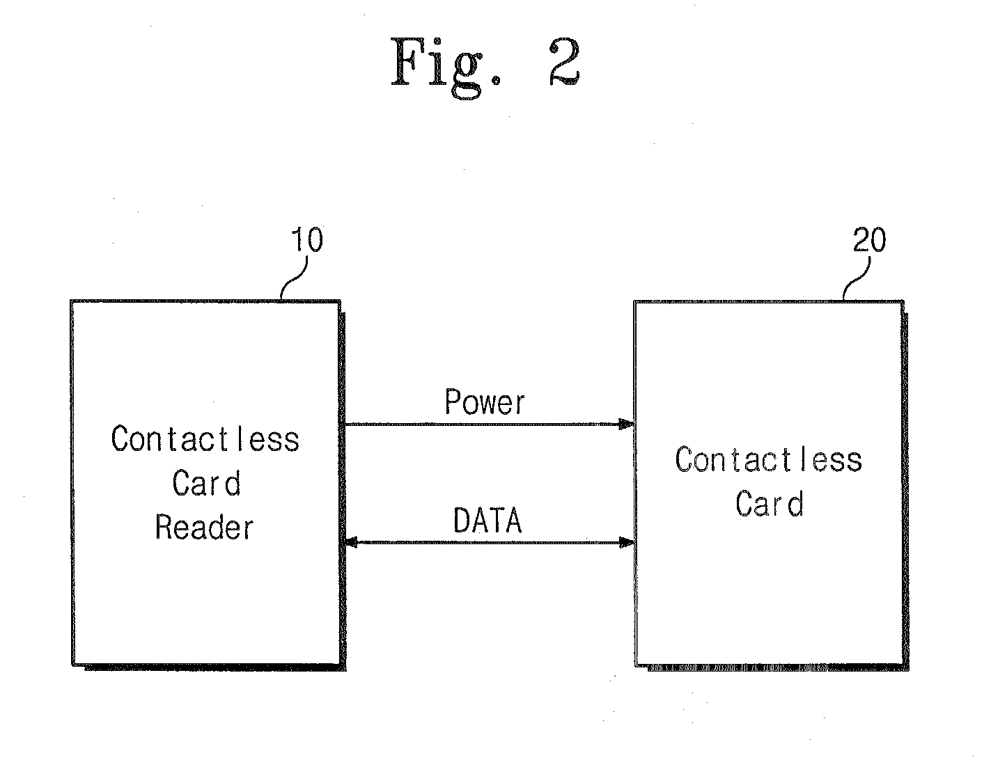
[0030]FIG. 2 is a schematic block diagram illustrating a contactless identification system in accordance with an exemplary embodiment of the present invention. Referring to FIG. 2, the contactless identification system is comprised of a contactless card reader 10, and a contactless smart card or tag, hereinafter, referred to as ‘smart card’20. The contactless card reader 10 continuously radiates an electr...


PUM


Abstract

A contactless card including an antenna coil, a resonant capacitor coupled between both end terminals of the antenna, a plurality of capacitors coupled in parallel with the terminals of the antenna correspondingly through switches, a shunt transistor coupled between the terminals of the antenna, forming a bypassing current path, a rectifier coupled between the terminals of the antenna, generating a DC voltage, and a control circuit sensing the DC voltage and controlling a gate voltage of the shunt transistor and on / off conditions of the switches in accordance with the sensed DC voltage.

Description

CROSS-REFERENCE TO RELATED APPLICATION[0001]This U.S. non-provisional patent application claims priority under 35 U.S.C. § 119 of Korean Patent Application No. 2005-05037 filed on Jan. 17, 2006, the entire contents of which are hereby incorporated by reference.BACKGROUND[0002]The present disclosure relates to contactless smart cards, contactless identification devices such as radio frequency identification tags (RFIDs), and contactless identification systems.[0003]Until recently, in the field of systemic identification technology, barcode and magnetic card systems have been widely used for credit cards, public telephone cards, and traffic cards. Such magnetic or barcode identification systems have a problem of degrading a rate of identification over time due to weakening magnetic force, physical damages, or other destructions. Thus, smart cards and radio frequency identification (RFID) tags are increasingly employed as advanced identification systems for overcoming the problems foun...

Claims


Application Information

Patent Timeline
IPC IPC(8): G06K19/06
CPCG06K19/0701G06K19/0723G06K19/0715B60P1/483B60P1/6427B60Y2306/13B60Y2200/144
Inventor JU, WON-CHUL
Owner SAMSUNG ELECTRONICS CO LTD
Learn More