
Method for diafiltration of a product and device for carrying out this method

a diafiltration and product technology, applied in the direction of membranes, ultrafiltration, cleaning using liquids, etc., can solve the problems of product washing, inability to adjust, and the quality and quantity of concentrate and permeate streams that are produced cannot be controlled

Inactive Publication Date: 2007-07-19
BUCHER GUYER MASCHFAB
View PDF6 Cites 22 Cited by
  • Summary
  • Abstract
  • Description
  • Claims
  • Application Information

AI Technical Summary

Benefits of technology

[0006] In addition, in a preferred embodiment of the method, the total fluid supply comprising the first and second fluid streams can be adjusted or automatically controlled, which makes it possible to adjust or automatically control the viscosity of the product stream leaving the membrane filtration means as retentate.
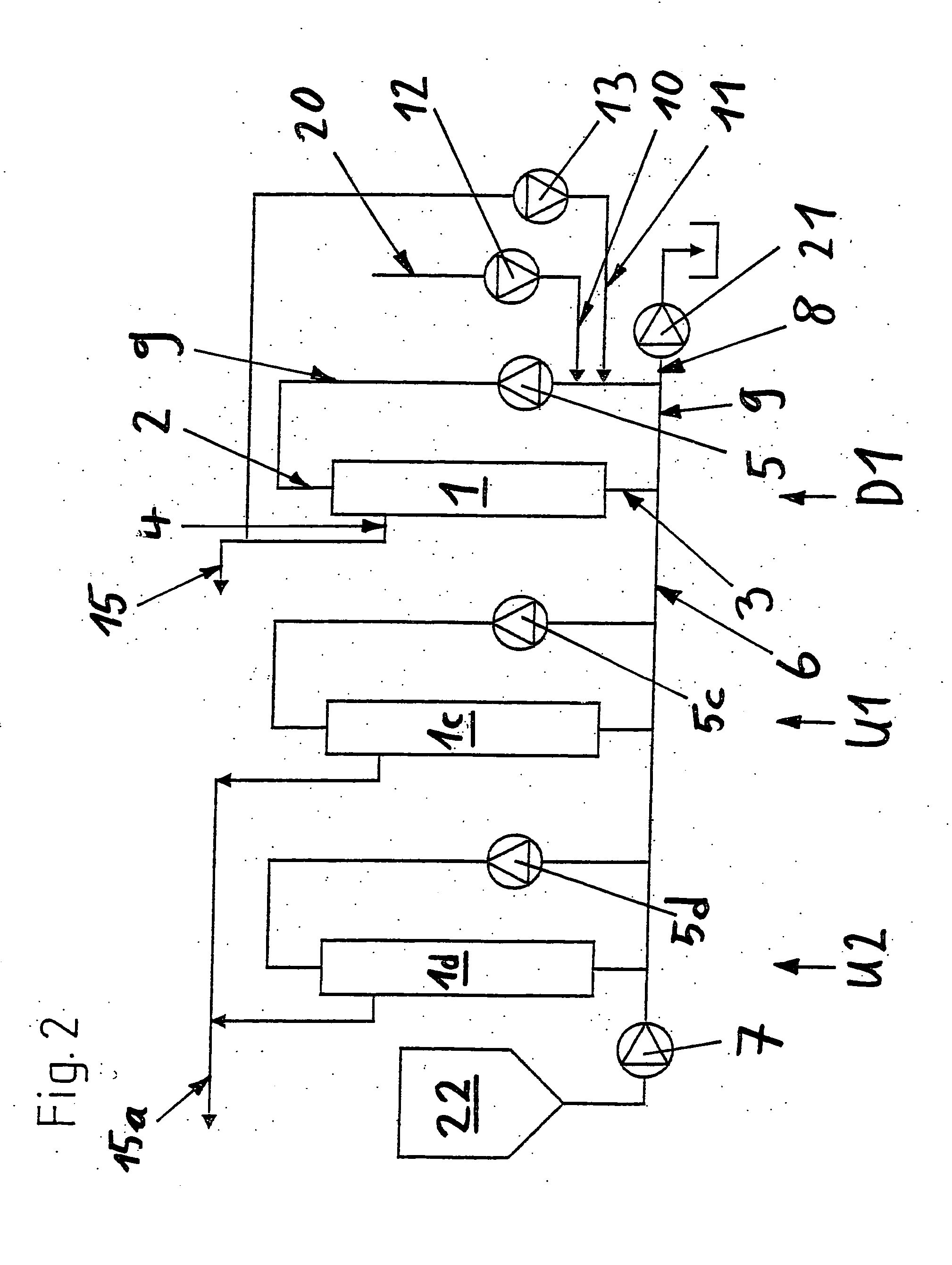
[0038] In yet another preferred embodiment, the filtration plant has nanofiltration, ultrafiltration, and / or microfiltration stages upstream of the diafiltration stages. Filtration plants of this type make it possible to separate liquid starting products economically and, if desired, practically completely into filterable and nonfilterable substances.

Problems solved by technology

All of the diafiltration methods presently known have the disadvantage that the degree of washing of the product, i.e., the degree of depletion of the filterable constituents in the product, cannot be adjusted under the steady-state operating conditions that are essential for continuously operating multistage, large-scale plants, so that the quality and quantity of the concentrate and permeate streams that are produced can be controlled only to a limited extent.

Method used


Image

  • Method for diafiltration of a product and device for carrying out this method
  • Method for diafiltration of a product and device for carrying out this method
  • Method for diafiltration of a product and device for carrying out this method

Examples


Embodiment Construction

[0004] Therefore, the objective of the invention is to develop methods and devices that do not have the disadvantages of the prior art or at least partially avoid these disadvantages.

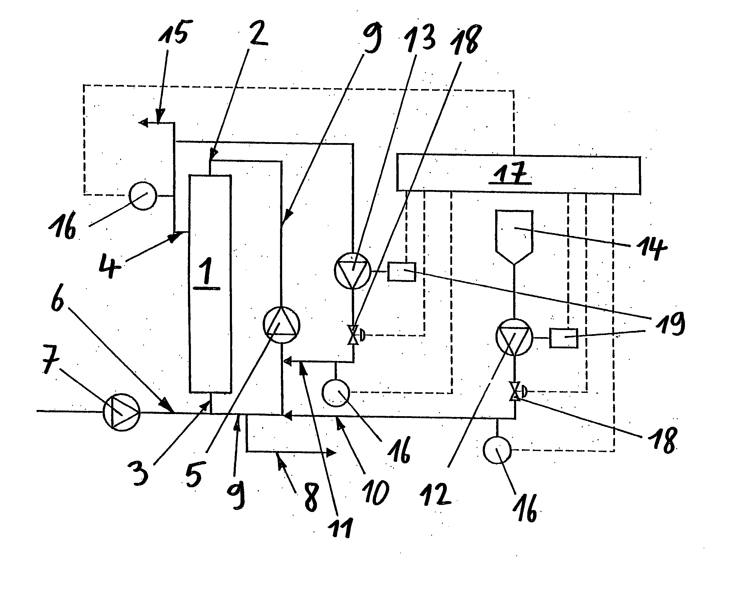
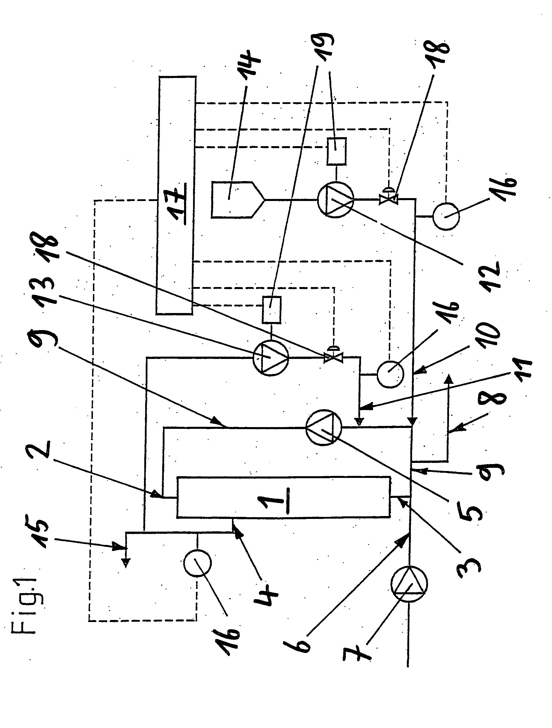
[0005] This objective is achieved by the method, the device, and the filtration plant in accordance with the independent claims. The first aspect of the invention concerns a method for the diafiltration of a product. In this method, a first fluid stream, which consists of a wash fluid that is external to the product, e.g., water, and a second fluid stream, which consists of a permeate that is derived from the product itself, e.g., permeate returned from the filtration means that are used or permeate produced by other filtration methods, are fed to a stream that consists of a product to be diafiltered, e.g., a stream of concentrated fruit juice, which is being fed to membrane filtration means to be filtered, in such a way that the product stream is diluted by the first and second fluid streams before it...


PUM


Abstract

The invention relates to a diafiltration stage for concentrated fruit juices, comprising a cross-flow filtration element (1). The product inlet (2) and the product outlet (3) of the filtration element (1) are united via a circulation pump (5) to form a product circuit, to which product is continuously supplied via a product supply line (6) and from which product can be continuously removed via a product discharge line (8). The permeate outlet (4) of the filtration element (1) is connected to the product circuit via a return line (1) comprising a permeate pump (13), enabling a desired amount of permeate to be returned to the product circuit. In addition, the stage comprises a wash-fluid supply line (10) that is equipped with a wash-fluid pump (12), which is used to supply a desired amount of water to the product circuit as wash fluid. The supplied amounts of permeate and water can be set independently of one another. Said diafiltration stage permits both the degree of washing of the product and the quality and amount of the product retentate and the permeate that is produced to be set and regulated within a wide range, even for fixed operating conditions, such as those required in continuous multi-stage large-scale installations.

Description

TECHNICAL FIELD [0001] The invention concerns a method for the diafiltration of a product, a device for carrying out this method, a filtration plant that uses this device, and the use of the device and the filtration plant in accordance with the introductory clauses of the independent claims. PRIOR ART [0002] Diafiltration is the filtration of a product with membrane filtration means with the addition of a wash fluid to the product, which causes the concentration of filterable constituents in the product to decrease, i.e., these substances are washed out without the nonfilterable constituents in the product necessarily being concentrated or the product becoming thickened. Wash fluids that are used are wash fluids external to the product, such as separately supplied water or solvent, permeate derived from the product itself, which is removed, for example, from a downstream diafiltration stage, or a mixture of the two (see also R. F. Madsen, Design of Sanitary and Sterile UF and Diafi...

Claims


Application Information

Patent Timeline
Patent Type & Authority Applications(United States)
IPC IPC(8): B08B3/00A23L2/08A23L2/74B01D61/14B01D61/16B01D61/18B01D61/22
CPCA23L2/082A23L2/74B01D61/142B01D61/145B01D61/16B01D61/18B01D2311/04B01D61/22B01D2311/14B01D2311/16B01D2311/25B01D61/146
Inventor ZIMMER, EDGAR
Owner BUCHER GUYER MASCHFAB
Learn More