
Method and apparatus for transmitting data frame using channel bonding in wireless LAN

a wireless lan and data frame technology, applied in data switching networks, multiplex communication, assessing restrictions, etc., can solve the problems of legacy stations not being able to analyze the ht format frame, the ineffective csma/ca method, and the inability to carry out virtual carrier sensing

Active Publication Date: 2007-07-12
SISVEL INT
View PDF9 Cites 69 Cited by
  • Summary
  • Abstract
  • Description
  • Claims
  • Application Information

AI Technical Summary

Benefits of technology

[0016]The present invention provides a method in which, even when an HT station transmits an HT format data frame through a wireless LAN in which legacy stations and HT stations coexist, the legacy stations can participate in a fair contention for medium access, and an apparatus therefor.
[0017]According to an aspect of the present invention, there is provided a method of transmitting an HT format data frame in a wireless LAN in which HT stations and legacy stations, which have different data transferring capabilities, coexist, the method comprising: adding a legacy format physical layer header including information, which indicates that a medium is being used while a frame exchange sequence is performed with respect to the HT format data frame, to the HT format data frame; transmitting the HT format data frame added with the legacy format physical layer header by using channel bonding; and broadcasting the legacy format control frames, which allow the stations to concurrently reset a waiting time for using the medium after recognizing the information, through each of channels used in the channel bonding when a time period elapses after the transmission is completed.
[0022]According to another aspect of the present invention, there is provided an apparatus for transmitting an HT format data frame in a wireless LAN in which HT stations and legacy stations, which have different data transferring capabilities, coexist, the apparatus comprising: a header inserting unit adding a legacy format physical layer header including information, which indicates that a medium is being used while a frame exchange sequence is performed with respect to the HT format data frame, into the HT format data frame; and a frame transmitting unit transmitting the HT format data frame with the legacy format physical layer header by using channel bonding, and broadcasting the legacy format control frames, which allow the stations to concurrently reset a waiting time for using the medium after recognizing the information, through each of channels used in the channel bonding when a time elapses after the transmission is completed.

Problems solved by technology

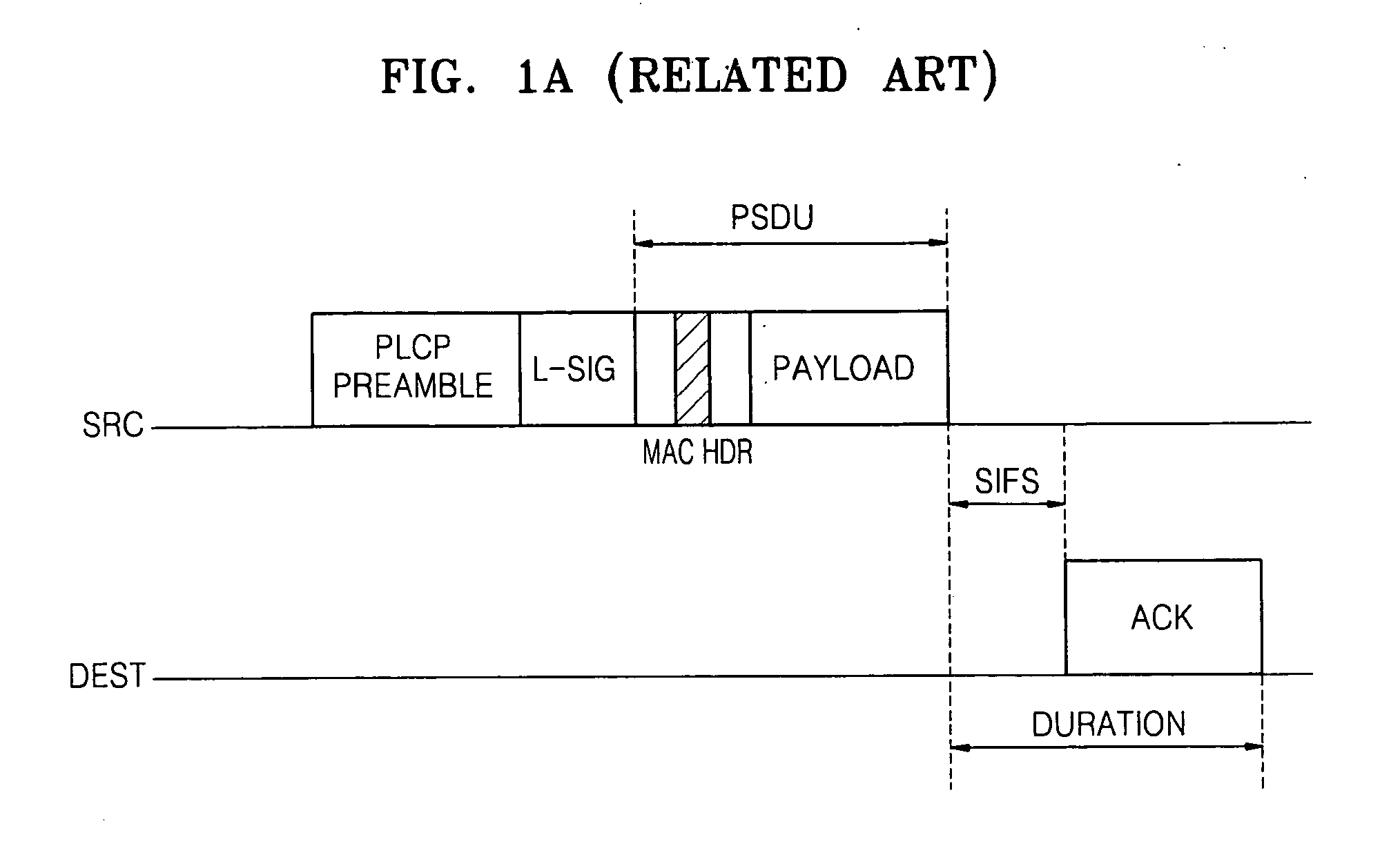
However, if a transmitting station sends data with a high data transfer rate (Tx Rate) and an error occurs due to an unstable channel condition, or a receiving station cannot cope with the high data transfer speed, virtual carrier sensing cannot be carried out because the received MPDU / PSDU cannot be analyzed.
Therefore, the CSMA / CA method becomes ineffective.
Accordingly, when a legacy station operating in accordance with the IEEE 802.11a, IEEE 802.11b, and / or IEEE 802.11g standards and a high throughput (HT) station having a higher capability than that of the legacy station (for example, an multi-input-multi-output (MIMO) station or a station using a channel bonding scheme) coexist in the wireless LAN, and when an HT format is sent, the legacy station cannot analyze the HT format frame, and thus virtual carrier sensing cannot be correctly carried out.
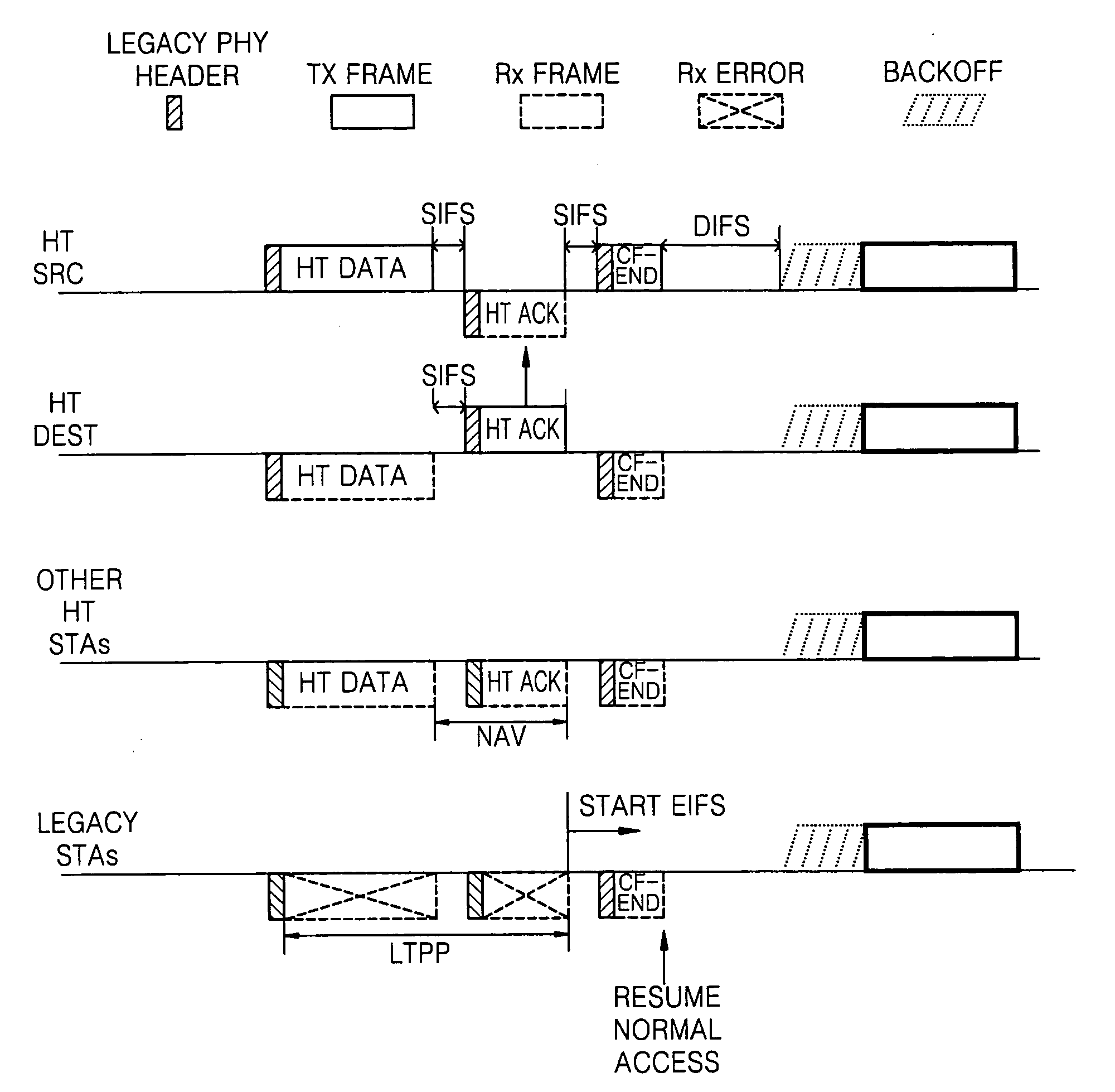
Referring to FIG. 3, when the LTPP mechanism is used, even if a legacy station can read the PHY header, the legacy station cannot read the next fields, that is, HT format, which leads to an error.
Accordingly, the legacy station becomes disadvantageous to other HT stations in terms of contending for medium access.

Method used


Image

  • Method and apparatus for transmitting data frame using channel bonding in wireless LAN
  • Method and apparatus for transmitting data frame using channel bonding in wireless LAN
  • Method and apparatus for transmitting data frame using channel bonding in wireless LAN

Examples


Embodiment Construction

[0032]FIG. 4 illustrates a method for allowing stations to have a fair contention for medium access by using an LTPP mechanism according to an exemplary embodiment of the present invention.

[0033]A transmission opportunity (TxOP) is a time required for transmitting a data frame. A CF-End frame is a message for canceling a remaining TxOP when a transmitting station that has obtained the TxOP by using a request-to-send / clear-to-send (RTS / CTS) frame exchange sequence has no frame to be sent even if the TxOP is still left. Stations which receive the CF-End recognize that a medium is available to be accessed. Referring to FIG. 4, the transmitting station broadcasts a legacy format CF-End frame when a short inter-frame space (SIFS) elapses after the transmitting station receives an ACK frame for an HT format data frame.

[0034]Since the CF-End frame is a message indicating availability of a medium, after receiving the CF-End frame, an HT station and a legacy station can participate in conten...


PUM


Abstract

A method and apparatus are provided for transmitting a data frame using channel bonding in a wireless local area network in which high throughput (HT) stations and legacy systems coexist. The method includes adding a legacy format physical layer header including information, which indicates that a medium is being used while a frame exchange sequence is performed with respect to the HT format data frame, to the HT format data frame, transmitting the HT format data frame with the physical layer header by using channel bonding, and broadcasting the legacy format CF-End frame through a plurality of channels used in the channel bonding. Accordingly, after a frame exchange sequence is completed, the legacy stations which use channels used in the channel bonding can participate in a fair contention for medium access.

Description

CROSS-REFERENCE TO RELATED PATENT APPLICATION[0001]This application claims priority from U.S. Provisional Patent Application No. 60 / 758,223, filed on Jan. 12, 2006 in the U.S. Patent and Trademark Office, and Korean Patent Application No. 10-2006-0032409, filed on Apr. 10, 2006 in the Korean Intellectual Property Office, the disclosures of which are incorporated herein in their entirety by reference.BACKGROUND OF THE INVENTION[0002]1. Field of the Invention[0003]Methods and apparatuses consistent with the present invention relate to a wireless local area network (LAN), and more particularly, to carrier sensing multiple access with collision avoidance (CSMA / CA) in a wireless LAN in which high throughput (HT) stations and IEEE 802.11 legacy systems coexist.[0004]2. Description of the Related Art[0005]Medium access control (MAC) using a carrier sensing multiple access with collision avoidance (CSMA / CA) method is used in a wireless LAN.[0006]In the CSMA / CA method, physical carrier sensi...

Claims


Application Information

Patent Timeline
IPC IPC(8): H04L12/56H04J3/02H04L47/22
CPCH04L47/10H04L47/14H04L47/22H04W48/12H04W74/002H04W84/02H04W74/0808H04W88/10H04L12/2865H04W74/0816H04W74/08H04W84/12H04W8/04
Inventor KWON, CHANG-YEUL
Owner SISVEL INT
Learn More