
Gain calculating device

a calculating device and gain technology, applied in the field of gain calculating devices, can solve the problems of low degree of precision inability to compute an appropriate white balance gain, and inability to achieve high degree of reliability in estimating the contribution of strobe light, so as to achieve preferable white balance gain and high reliability. the effect of contribution

Inactive Publication Date: 2007-07-05
EASTMAN KODAK CO
View PDF3 Cites 15 Cited by
  • Summary
  • Abstract
  • Description
  • Claims
  • Application Information

AI Technical Summary

Benefits of technology

[0026]According to the present invention, the degree of contribution of strobe light is assumed on the basis of an actually-captured image, and hence a highly-reliable degree of contribution of strobe light is obtained. Consequently, a more preferable white balance gain can be obtained.

Problems solved by technology

Therefore, when strobe light has not sufficiently reached the subject or when strobe light has been radiated with excessive intensity on the subject, there arises a problem of a failure to compute an appropriate white balance gain.
However, any of these conventional techniques involves estimating the degree of contribution of strobe light from information extracted from factors other than a captured image such as a distance to a subject and information about flash light.
Therefore, the conventional techniques cannot be said to have a high degree of precision in estimating the degree of contribution of strobe light.
The low degree of precision in estimating the degree of contribution of strobe light poses difficulty in performing white balance processing suitable for strobe illuminated photography.

Method used


Image

  • Gain calculating device
  • Gain calculating device
  • Gain calculating device

Examples


Embodiment Construction

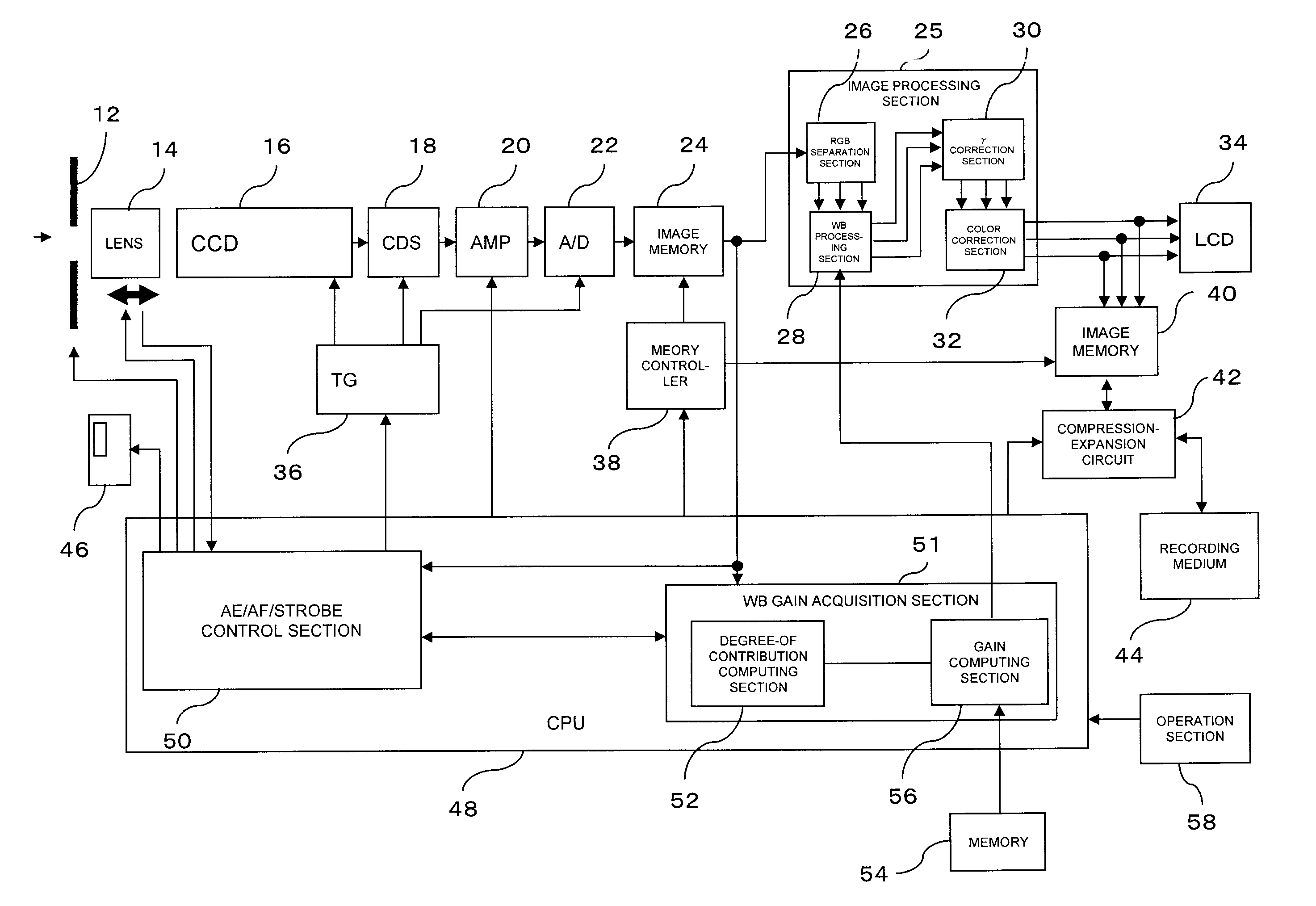
[0039]An embodiment of the present invention will be hereinbelow described by reference to the drawings. FIG. 1 is a block diagram showing the configuration of a digital camera 10 which is an embodiment of the present invention. Light from a field (hereinafter simply called “light”), which has entered by way of an aperture member 12 and a lens 14, comes into a focus on a CCD 16, which is an image-capturing device. The amount of opening of the aperture member 12 and the amount of movement of the lens 14 are controlled by a CPU 48. The CCD 16 converts the input light into an electrical signal, and outputs the thus-converted electrical signal as captured-image data. Timing at which the CCD 16 performs photoelectric conversion is controlled by the CPU 48 via a timing generator (TG) 36. The CCD 16 always stores and sweeps electric charges at given intervals in order to acquire a preview image to be displayed on an LCD 34. Moreover, when a user's command for capturing an image is input, p...


PUM


Abstract

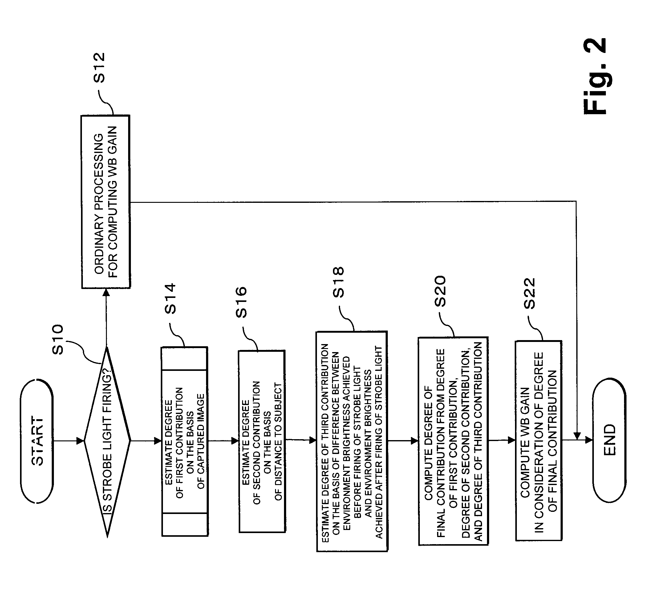
A more preferable WB gain is calculated during strobe illuminated photography. When a WB gain for an image captured through strobe illuminated photography is calculated, the degree of contribution of strobe light is first estimated. When the degree of contribution is estimated, the image is first divided into a plurality of blocks, and typical brightness values and typical color values of the respective blocks are determined (S23). Subsequently, the highest-brightness block among the blocks analogous to the color of strobe light is identified as a strobe color block (S26). When there is a strobe color block, the degree of contribution of strobe light is estimated on the basis of the position of the strobe color block, a difference between the brightness of the strobe color block and the brightnesses of other blocks, and the like (S32 to S48). Meanwhile, when there is no strobe color block, the degree of contribution is estimated on the basis of the position of the highest-brightness block having the highest typical brightness value among the plurality of blocks (S28, S30).

Description

CROSS REFERENCE TO RELATED APPLICATIONS[0001]This application claims priority to Japanese Patent Application No. 2006-831 filed on Jan. 5, 2006, which is incorporated herein by reference in its entirety.BACKGROUND OF THE INVENTION[0002]1. Field of the Invention[0003]The present invention relates to a gain calculating device for calculating a white balance gain suitable for at least an image captured through strobe illuminated photography.[0004]2. Related Art[0005]In the field of cameras, there has been widely known a white balance technique for correcting the color of a captured image according to the type of a light source employed at the time of capture of the image, and the like. This technique is an image processing technique for eliminating a discrepancy between an impression which a photographer had during photographing action and an impression given by an output image, which is caused by the color of the light source employed during photography.[0006]A technique for taking in...

Claims


Application Information

Patent Timeline
IPC IPC(8): G03B7/00H04N9/04
CPCG03B7/16H04N9/735H04N5/2354H04N5/2351H04N23/71H04N23/74H04N23/88
Inventor TAKAHASHI, KAZUNOBUYOSHIKAWA, SUMITO
Owner EASTMAN KODAK CO
Learn More