Television receiver with a flat screen display

Inactive Publication Date: 2007-07-05
MICRONAS
View PDF0 Cites 2 Cited by
  • Summary
  • Abstract
  • Description
  • Claims
  • Application Information

AI Technical Summary

Benefits of technology

[0005] A component interface unit spatially separated from a flat panel television display receives external connections that are connected to the television receiver through a bus system. The term “high-capacity” here means that the bus connection is of the highest frequency possible in order to carr

Problems solved by technology

In comparison with conventional cable connections, a bus of this type is relatively inconspicuous and can easily be routed between the s

Method used


Image

  • Television receiver with a flat screen display
  • Television receiver with a flat screen display
  • Television receiver with a flat screen display

Examples


Embodiment Construction

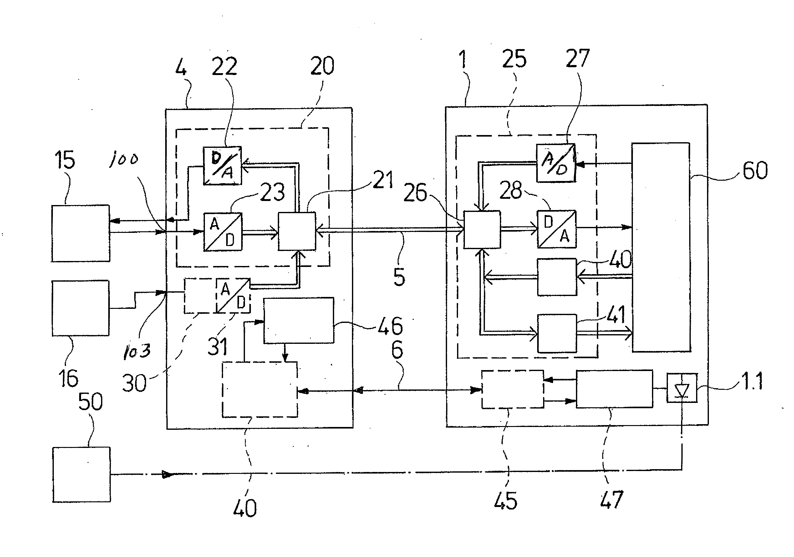
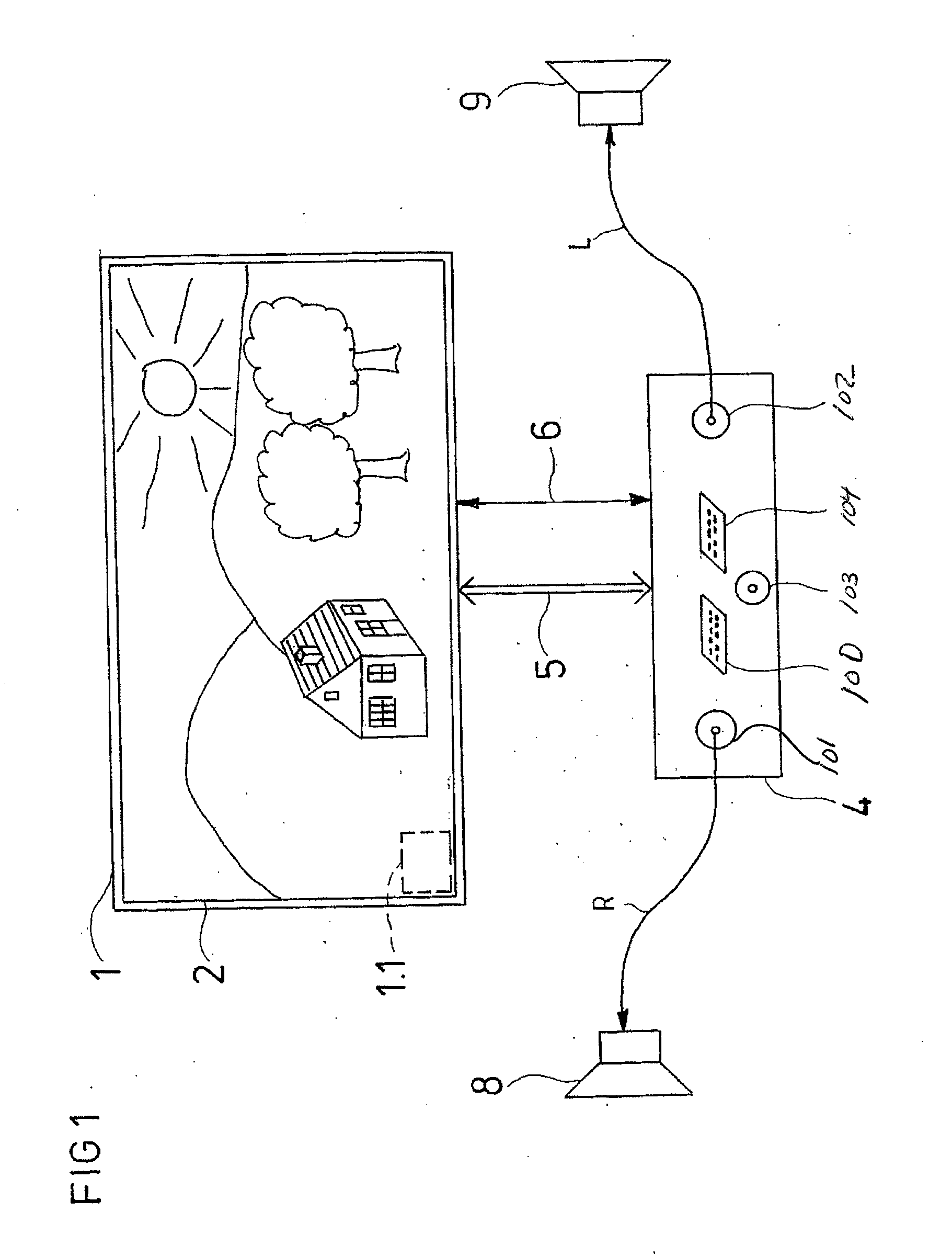
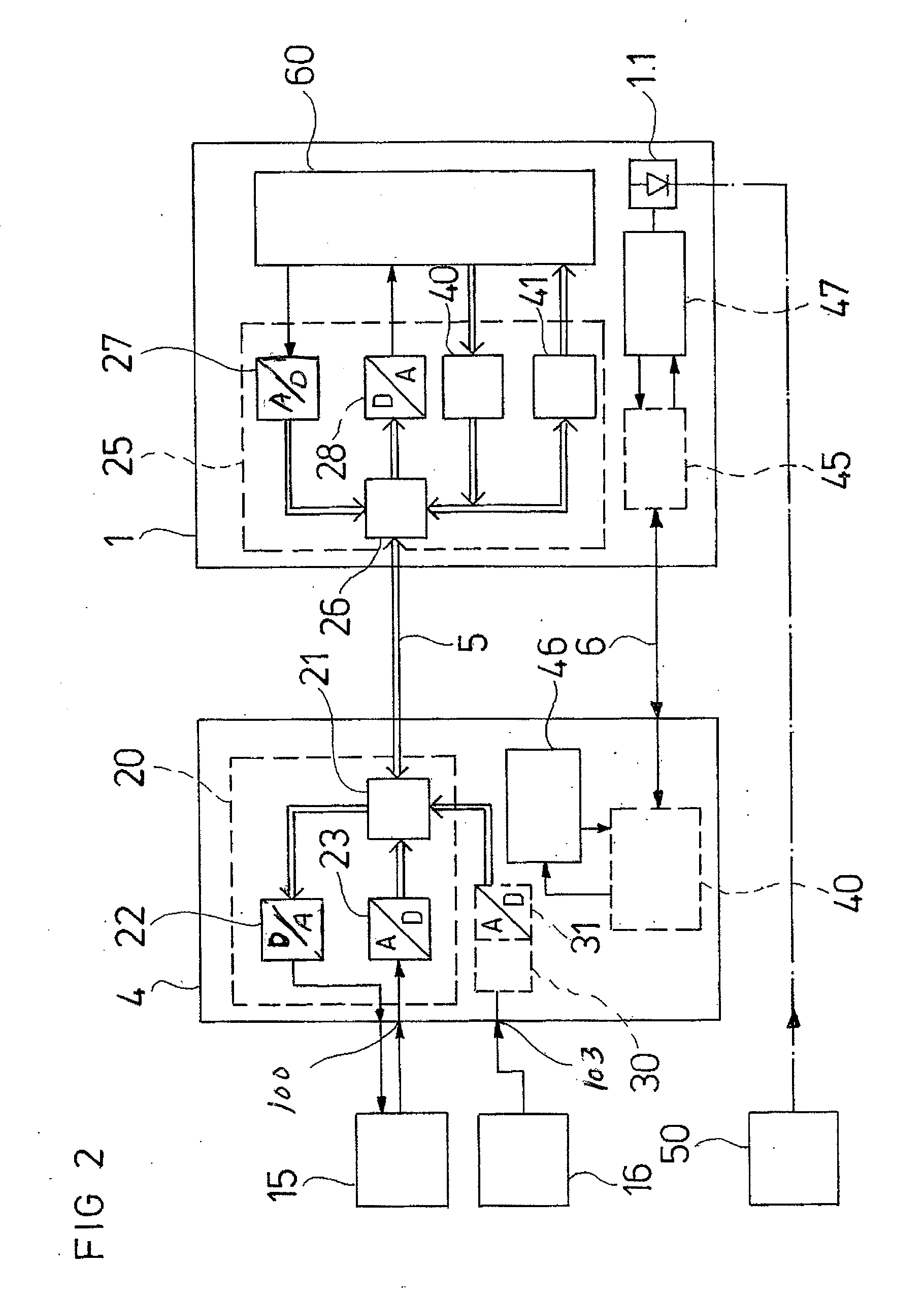
[0010]FIG. 1 schematically illustrates a television receiver 1 with an associated flat screen display 2. Flat screen displays of this type provide a low profile depth suitable for hanging on a wall like a picture. The associated electronics may be accommodated in the flat television receiver 1. Difficulties are caused, however, by loudspeakers 8, 9 and the various connection sockets 100-104 for external devices. In principle, the connection sockets can continue to be inserted on the rear side of the flat television receiver 1, or on the lateral surfaces thereof, and are thus invisible from the front. In the case of a wall mounting, however, the cables and associated plugs to be connected detract from the overall visual impression, in particular, if the cables have to be routed on the rear since the television receiver must then be moved away from the wall.

[0011] These disadvantages are eliminated by the spatial separation of connection sockets 100-104 from the television receiver 1...


PUM


Abstract

Television receiver comprising a flat screen display which has a component interface unit spatially separate from the television receiver for the external terminals, such as, for example, SCART sockets or speaker terminals, the component interface unit being connected through at least one high-capacity bus connection to the television receiver. The bus connection is connected in the spatially separate component interface unit to first bus interfaces for signals to be fed in and out, and is connected in the television receiver to second bus interfaces.

Description

PRIORITY INFORMATION [0001] This patent application claims priority from German patent application 10 2006 000 890.1 filed Jan. 4, 2006, which is hereby incorporated by reference. BACKGROUND INFORMATION [0002] The invention relates to a television receiver with a flat screen display. [0003] Flat panel televisions (e.g., LCD or plasma) are suitable for hanging on a wall analogous to a picture. One disadvantage with this mounting is that the connection sockets installed on the side or at the rear are no longer readily accessible, and in particular, the various signal cables to the speakers, video recorder, and DVD player disturb the visual impression as a result of the wall mounting. While the various cables can in fact be accommodated in a cable conduit mountable on the wall, the size required nevertheless makes an objectionable impression. [0004] There is a need for an improved technique for connecting television input and output devices such as cable and satellite receivers and spe...

Claims


Application Information

Patent Timeline
IPC IPC(8): H04N5/44H04N5/64
CPCH04N21/43632H04N5/44
Inventor SIEBEN, ULRICHTEMERINAC, MIODRAG
Owner MICRONAS
Why Eureka
Try Eureka