Stabilizer to aid in installation and removal of a transmission

Inactive Publication Date: 2007-07-05
CHAPMAN JARVIS A +1
View PDF23 Cites 1 Cited by
  • Summary
  • Abstract
  • Description
  • Claims
  • Application Information

AI Technical Summary

Benefits of technology

[0008] The stabilizer that aids in the installation and removal of transmissions, for example, the E40D, from vehicles is a receptacle with a bottom and a sidewall. The sidewall is shaped to support the underside of the transmission. When the transmission is set in the stabilizer, the top edge of the sidewall conforms snugly to the underside of the transmission. The route the top edge of the sidewall takes around the transmission supports the uneven weight of the transmission and allows that weight to be spread out more smoothly across the bottom of the stabilizer.
[0009] The bottom of the stabilizer is flat so as to rest in a stable manner on the lift platform of a hydraulic jack. The stabilizer may rest on the lift platform without being bolted to the lift platform. Because the user does not need to bolt the stabilizer to the platform, the transmission can be changed quickly and the hydraulic jack can be used for other purposes, and be transported away in a more efficient manner. The stabilizer is lightweight, but sturdy enough to support the weight of a transmission. The transmission may also be kept in the stabilizer while the transmission is out of the vehicle but not being worked on, which may help to prevent the transmission from being accidentally knocked over while positioned in a busy workplace.
[0010] Accordingly, it is a principal object of the invention to allow one person to quickly and safely remove a transmission from a vehicle for repair, then re-install the transmission when repaired.

Problems solved by technology

However, if repair work is needed, the access opening is usually not large enough for access to perform the repair work.
Modern vehicle transmissions, and in particular the E40D transmission, are very large and may weigh hundreds of pounds.
Often, modern transmissions such as the E40D do not have flat surfaces on which they can be set in a stable manner.
Therefore, they are very unstable when set onto the flat lift platform on the hydraulic jack.
If workers are called away from other tasks to help hold a transmission, they are not completing the tasks they abandoned as quickly.
For a busy automotive repair shop, both of these methods are inefficient and waste valuable man-hours during a typical transmission repair service.

Method used


Image

  • Stabilizer to aid in installation and removal of a transmission
  • Stabilizer to aid in installation and removal of a transmission
  • Stabilizer to aid in installation and removal of a transmission

Examples


Embodiment Construction

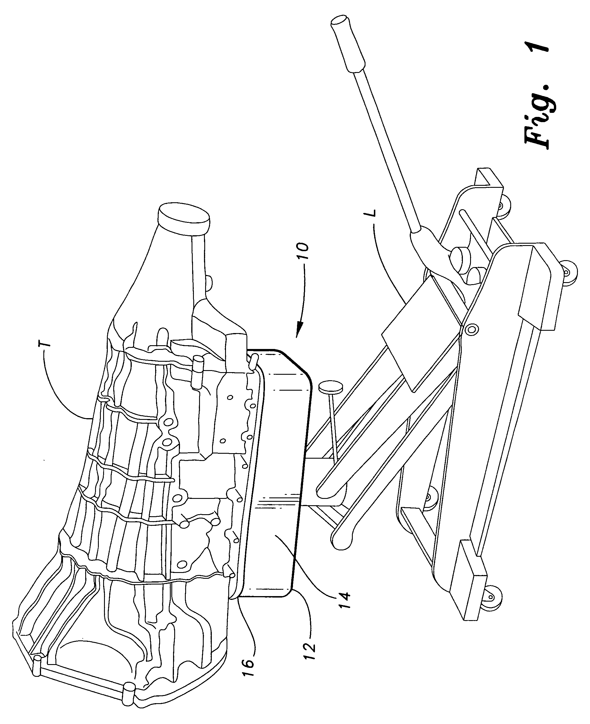
[0015] The present invention is a transmission stabilizer, designated generally as 10 in the drawings. As shown in FIG. 1, the stabilizer 10 is designed to support a transmission T during the removal and installation of the transmission T from a vehicle. One such type of transmission to be supported by device 10 could be the E40D, for example. The stabilizer 10 has a bottom 12 that is flat so that the bottom 12 may rest safely on the lift platform of a hydraulic jack L.

[0016] As shown in FIG. 2, a sidewall 14 extends around the bottom 12 and projects upwardly therefrom. The transmission T rests in the stabilizer 10 such that the top edge 16 of the sidewall 14 supports the transmission T. The top edge 16 of the sidewall 14 is shaped so that the top edge 16 supports the transmission T in a balanced, stable manner.

[0017] When a transmission T, such as an E40D, must be repaired, the stabilizer 10 is placed on the lift platform of a hydraulic jack L, then raised until it is positioned ...


PUM


Abstract

A stabilizer to aid in the installation and removal of transmissions from vehicles is a receptacle with a bottom and a sidewall. The sidewall is shaped and of sufficient strength to support the underside of the transmission while the bottom is flat so as to rest in a stable manner on the lift platform of a hydraulic jack. The stabilizer allows one person to quickly and safely remove a transmission from a vehicle for repair, then re-install the transmission when repaired.

Description

BACKGROUND OF THE INVENTION [0001] 1. Field of the Invention [0002] The present invention relates to tools. More specifically, the device is a tool used to support and stabilize a vehicle transmission during installation and removal of the transmission from the vehicle. [0003] 2. Description of the Related Art [0004] Many automotive transmissions have removable access openings underneath the transmission housing to allow the transmission to be inspected for normal wear. However, if repair work is needed, the access opening is usually not large enough for access to perform the repair work. The transmission must be removed from the underside of the vehicle in order for repair work to be accomplished. [0005] Modern vehicle transmissions, and in particular the E40D transmission, are very large and may weigh hundreds of pounds. Due to this weight, the transmission must be supported mechanically, usually through a hydraulic jack. The jack rests on the floor and has an arm extending from i...

Claims


Application Information

Patent Timeline
IPC IPC(8): B65D85/68
CPCB66F5/04
Inventor CHAPMAN, JARVIS A.MAYENSCHEIN, CHARLES
Owner CHAPMAN JARVIS A
Why Eureka
Try Eureka