Wet-type multi-plate clutch
a multi-plate clutch and wet-type technology, applied in the direction of fluid gearings, friction linings, gearings, etc., can solve the problems of poor performance of other friction materials, large heat generation, and insufficient multi-plate clutches used in slip control, etc., to achieve efficient lubrication, high capacity, and great engagement torque capacity
- Summary
- Abstract
- Description
- Claims
- Application Information
AI Technical Summary
Benefits of technology
Problems solved by technology
Method used
Image


Examples
first embodiment
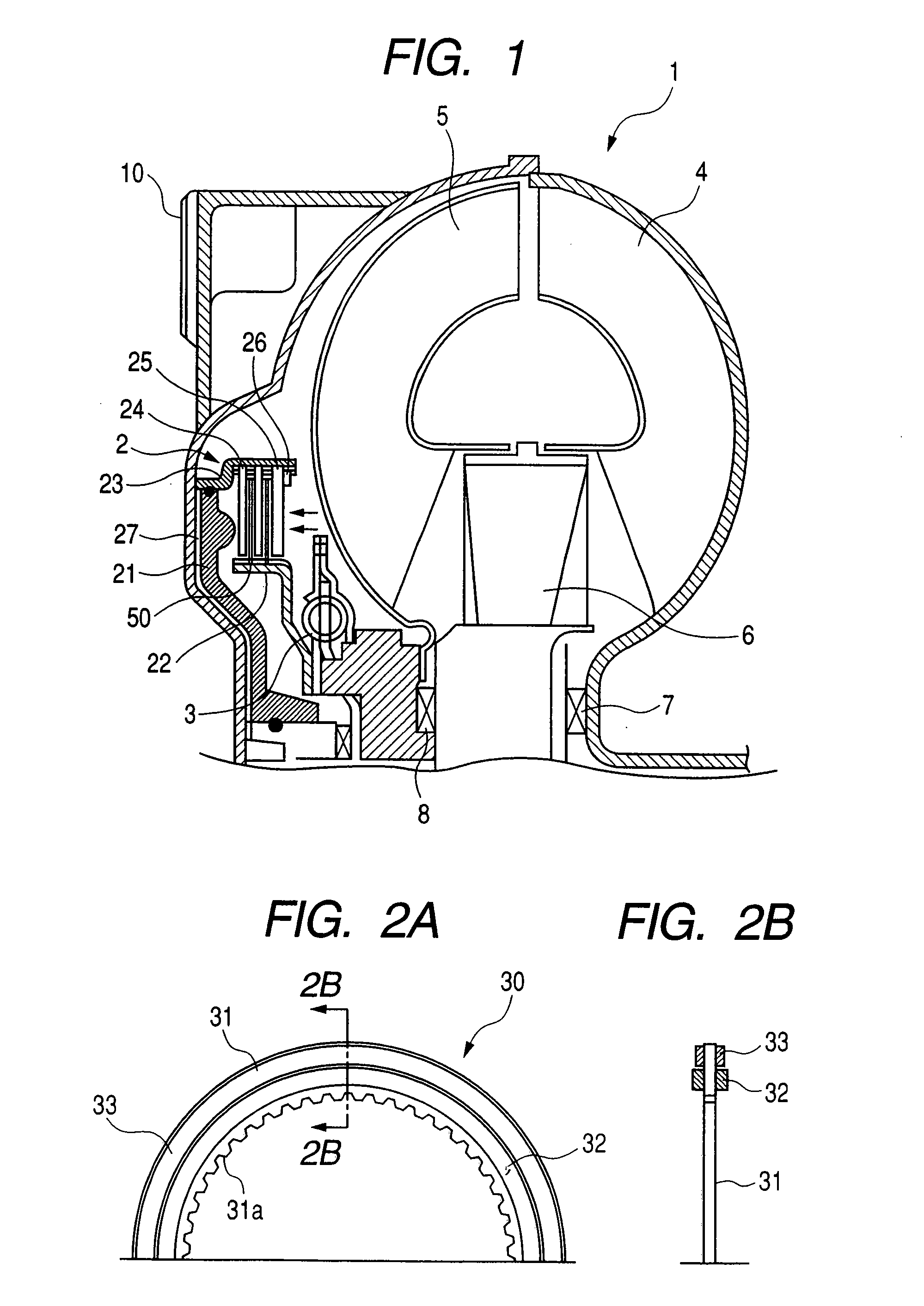
[0034]FIGS. 2A and 2B are views showing a friction plate according to a first embodiment of the present invention. FIG. 2A is a partial front view of the friction plate and FIG. 2B is a partial sectional view taken along the line A-A in FIG. 2A.
[0035] The friction plate 30 is constituted by sticking first and second friction materials onto a substantially annular core plate 31 made of steel. The core plate 31 is provided at its inner periphery with splines and is fitted to a rotary member (not shown).
[0036] On each of friction surfaces at both axial directions of the core plate 31, a substantially first annular friction material 32 is stuck at an inner diameter side and a substantially annular second friction material 33 is stuck at an outer diameter side. The first friction material 32 and the second friction material 33 are disposed adjacent to each other in a radial direction.
[0037] As can be seen from FIG. 2B, the first friction material 32 has an axial thickness greater than...
second embodiment
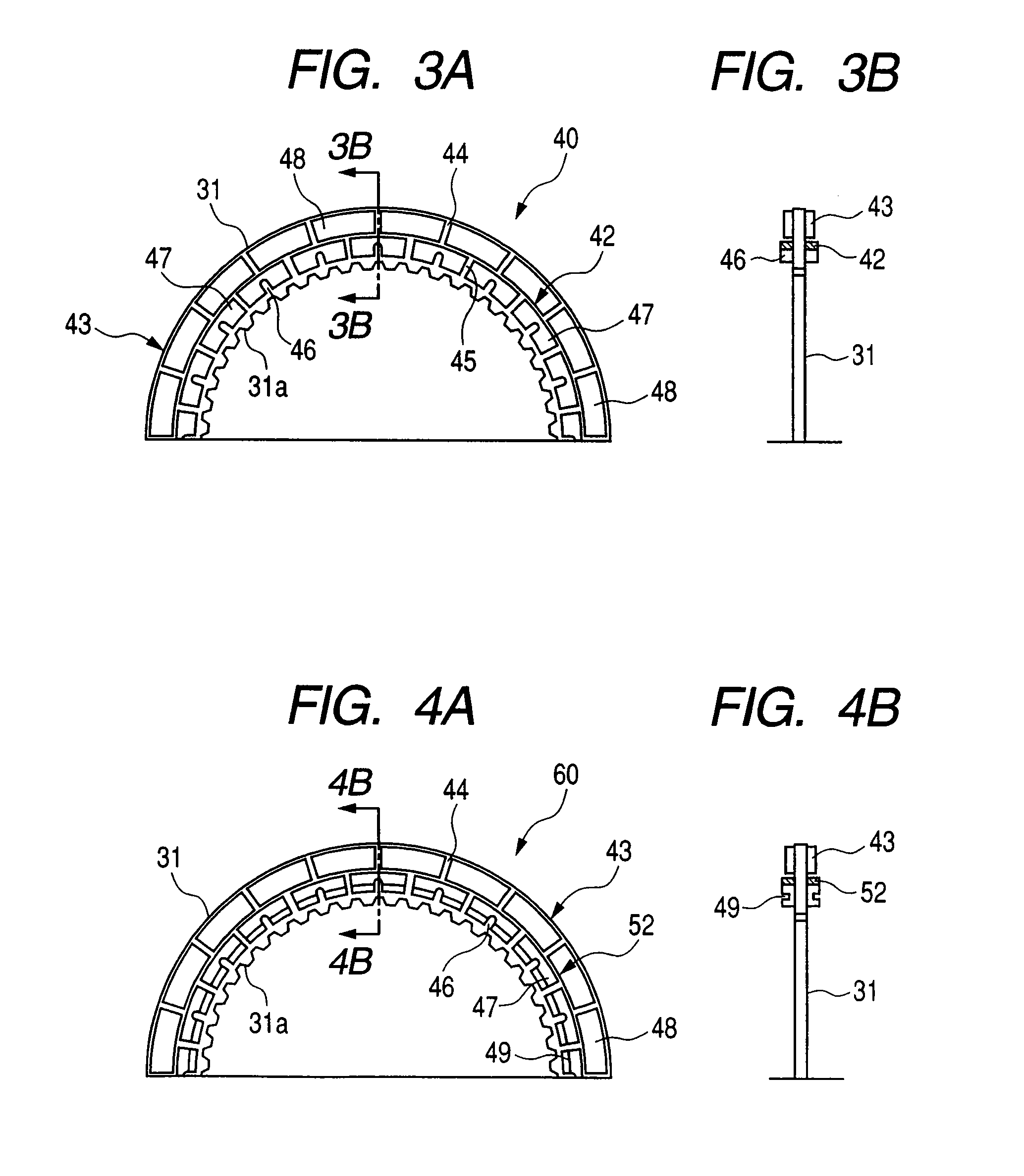
[0039]FIGS. 3A and 3B are views showing a friction plate according to a second embodiment of the present invention. FIG. 3A is a partial front view of the friction plate and FIG. 3B is a partial sectional view taken along the line B-B in FIG. 3A.
[0040] Similar to the first embodiment, a friction plate 40 is constituted by sticking first and second friction materials onto a substantially annular core plate 31 made of steel. The core plate 31 is provided at its inner periphery with splines 31a and if fitted on a rotary member (not shown).
[0041] On each of both axial friction surfaces of the core plate 31, the first friction material 42 is stuck at an inner diameter side and the second friction material 43 is stuck at an outer diameter side by adhesives. The first friction material 42 and the second friction material 43 are disposed adjacent to each other in a radial direction.
[0042] In the first embodiment, while the first and second friction materials are substantially annular and...
third embodiment
[0048]FIGS. 4A and 4B are views showing a friction plate according to a third embodiment of the present invention. FIG. 4A is a partial front view of the friction plate and FIG. 4B is a partial sectional view taken along the line C-C in FIG. 4A.
[0049] A third embodiment is fundamentally similar to the second embodiment, and, thus, only differences will be described. In the third embodiment, a construction of a first friction material 52 differs from that of the friction material of the second embodiment. In the first friction material, plural friction material segments 47 are stuck on the friction surface of the core plate 31 at a predetermined interval along a circumferential direction.
[0050] Each first friction material segment 47 is provided at its surface with a circumferential groove 49 extending in the circumferential direction. The circumferential groove 49 intersects with the groove 46 and the spaces 45 to be communicated with them. As shown in FIG. 4B, similar to the firs...
PUM
 Abstract
Description
Claims
Application Information
 - R&D
- Intellectual Property
- Life Sciences
- Materials
- Tech Scout
- Unparalleled Data Quality
- Higher Quality Content
- 60% Fewer Hallucinations
Browse by: Latest US Patents, China's latest patents, Technical Efficacy Thesaurus, Application Domain, Technology Topic, Popular Technical Reports.
© 2025 PatSnap. All rights reserved.Legal|Privacy policy|Modern Slavery Act Transparency Statement|Sitemap|About US| Contact US: help@patsnap.com