
Process for manufacturing RFID label

a technology of smart labels and manufacturing processes, applied in the direction of mechanical actuation of burglar alarms, instruments, paper/cardboard articles, etc., to achieve the effect of efficient, accurate and reliable processes

Inactive Publication Date: 2007-07-05
INTERMEC IP
View PDF14 Cites 17 Cited by
  • Summary
  • Abstract
  • Description
  • Claims
  • Application Information

AI Technical Summary

Benefits of technology

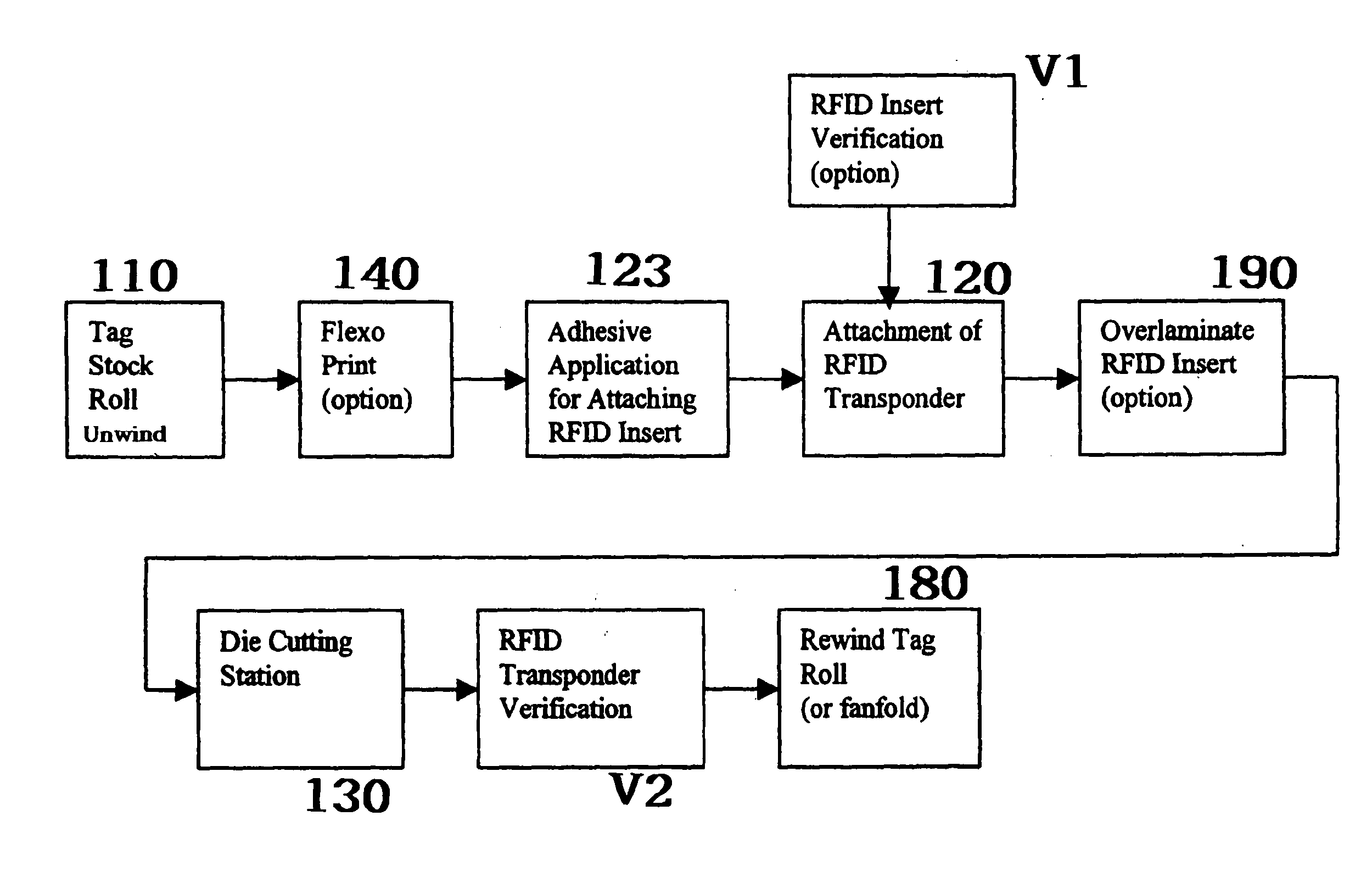
[0011] The present invention is an automated process for manufacturing smart labels and tags having an RFID transponder. The inventive method provides an efficient, accurate and reliable process for manufacturing labels or tags with RFID transponders using one pass on a label converting press equipped with an in-line insertion station.

Problems solved by technology

Because RFID transponders are relatively fragile and bending can cause cracking or damage to their circuits, the insertion equipment must be capable of introducing the RFID transponder in a manner that protects the chip and antenna.

Method used


Image

  • Process for manufacturing RFID label
  • Process for manufacturing RFID label
  • Process for manufacturing RFID label

Examples


Embodiment Construction

[0028] The present invention is an automated process for manufacturing smart labels or tags having an RFID transponder. The inventive method provides an efficient, accurate and reliable process for successfully manufacturing RFID labels or tags using one pass on a label converting press 100 equipped with an in-line insertion station 120.

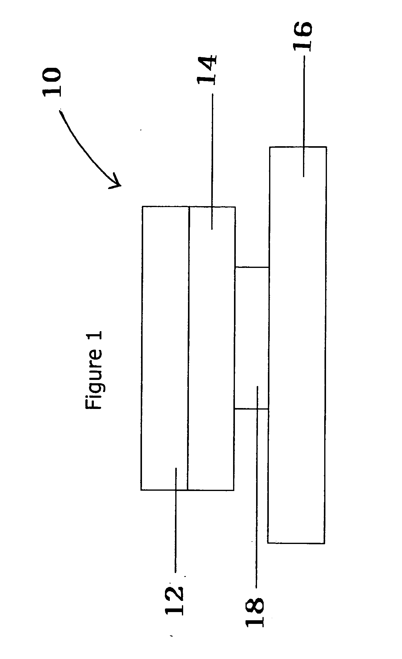
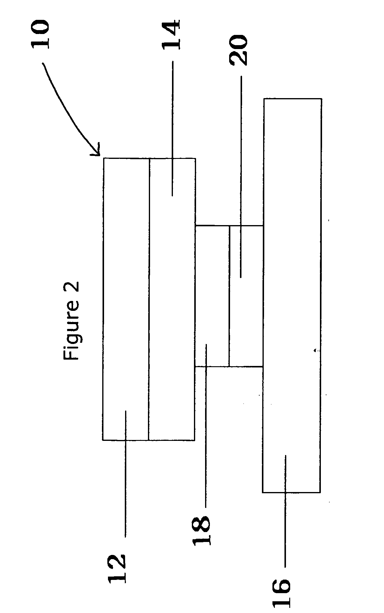
[0029] A smart label 10 is shown in FIG. 1. Smart label 10 is a layered construction comprising a label face sheet 12, a release liner 16, an adhesive layer 14 between the label face sheet 12 and the liner 16 and an RFID transponder 18 between the label face sheet 12 with adhesive 14 and the liner 16. Optionally, there may be an adhesive layer 20 or adhesive patch on the back of the RFID transponder, multiple inserts 18, multiple label face sheets 12 and / or multiple liner 16 layers. Multiple label face sheets 12 and multiple liner sheets 16 are useful in piggyback or multi-layer forms.

[0030] An RFID transponder 18 (also referred to as an RFID tag, ...


PUM


Abstract

An automated process for manufacturing smart labels having a radio frequency identification transponder (RFID) transponder. The inventive method accurately and reliably inserts RFID transponders into labels on onto tags 70 in one pass on a label press 100 equipped with an in-line insertion station 120. The transponders may be provided in continuous supply reel and singulated as needed to form discrete terms transponders or single transponders may be provided in the hopper. The label is delaminated and the transponders are individually applied directly to the adhesive side of the labels in the machine direction of the moving web. The label liner is then relaminated back onto the label face stock sandwiching the RFID transponder between the liner and the label stock.

Description

BACKGROUND OF THE INVENTION [0001] 1. Field of the Invention [0002] The present invention relates to an automated process for manufacturing smart labels having radio frequency transponders (RFID) capable of interrogation by reader. [0003] 2. Description of the Related Art [0004] Bar codes have historically been used for tracking and identifying articles. While bar-code labels are relatively inexpensive, they have limitations. Barcode labels require a direct line of sight with a barcode scanner in order to be effective. Barcode labels can only be read one at a time. Once the barcode is printed, the data stored within the bar code cannot be updated or modified. The amount of information that can be contained in the bar code is limited. [0005] Commonly used barcodes include 1D barcodes and 2D or matrix barcodes. 1D bar code symbologies have two or more different widths of straight-line black bars. The spaces and bars of a 1D bar code are a simplified language that can be understood by ...

Claims


Application Information

Patent Timeline
Patent Type & Authority Applications(United States)
IPC IPC(8): B65C9/18G08B13/14
CPCB31D1/025G06K19/0776G06K19/07749G06K19/07718
Inventor ADAMS, MATTARGADINE, OTTOTAYLOR, DOUGCONWELL, KEVINO'BRIEN, RICKPETERNEL, JIM
Owner INTERMEC IP
Learn More