
Electronic control transformer using DC link voltage

Inactive Publication Date: 2007-07-05
YORK INT
View PDF62 Cites 50 Cited by
  • Summary
  • Abstract
  • Description
  • Claims
  • Application Information

AI Technical Summary

Benefits of technology

[0015] One advantage of the present invention is that the electronic transformer is connected to a variable speed drive with improved ride-through capabilities thereby providing ride-through capability to auxiliary components of the chiller system and providing improved reliability of the chiller system.
[0016] Another advantage of the present invention is the use of a single electronic control transformer for powering the chiller controls, that is independent of the input AC voltage magnitude and input frequency to the VSD equipped chiller system.
[0017] Another advantage of the present invention is that the electronic transformer eliminates the need for a conventional control transformer and provides a common source of electrical power for the entire chiller system.

Problems solved by technology

The use of line voltages and frequencies typically limited the options for modulating the capacity of the compressors to less efficient mechanical devices such as inlet guide vanes and slide valves, as a result of the motor being limited to one operating speed that was based on the input frequency to the motor.
The sag or interruption, if sufficient in magnitude and / or duration, may cause the chiller system's contactors or relays to drop out, or cause the control panel or pumps to shut down, resulting in interruption of chiller system operation.
The VSD supplying the compressor is also subject to input voltage sags and interruptions for the same reason.
Very often, however, the ride-through capability is insufficient to maintain the chiller operation for input voltage sags or interruptions greater than a few cycles on a 60 Hz utility line.
In the case where the VSD is configured with ride-through capability, the control transformer can leave the chiller system vulnerable to a voltage sag, even though the VSD and compressor motor may survive the voltage sag.
One limitation of chiller systems having separate AC input power sources for the compressor and the auxiliary devices is that if either the VSD output voltage or the control voltage sags or experiences a brief interruption, then the chiller system fails.
Another limitation of chiller systems having separate AC input control power sources for the compressor and the auxiliary devices is that different control transformers must be used for power systems having different distribution voltages, the design of the control transformer being dependent upon the input AC voltage and frequency supplied to the chiller system.

Method used


Image

  • Electronic control transformer using DC link voltage
  • Electronic control transformer using DC link voltage
  • Electronic control transformer using DC link voltage

Examples


Embodiment Construction

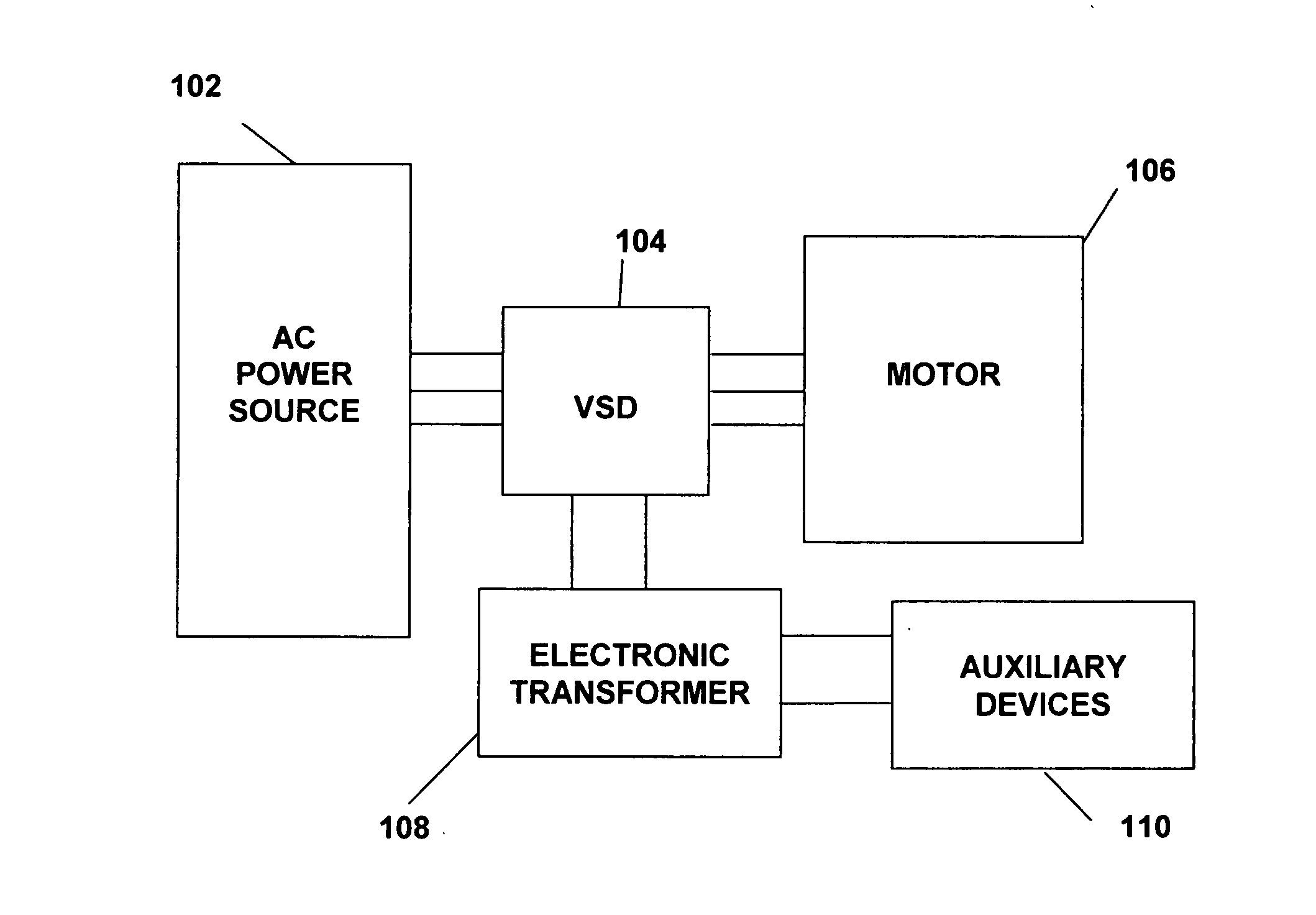
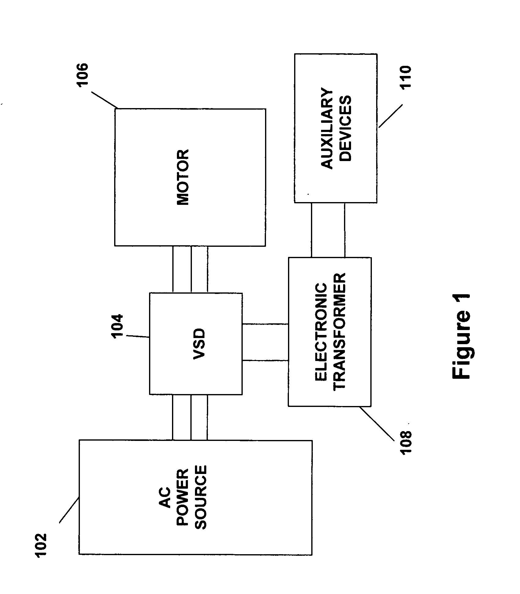
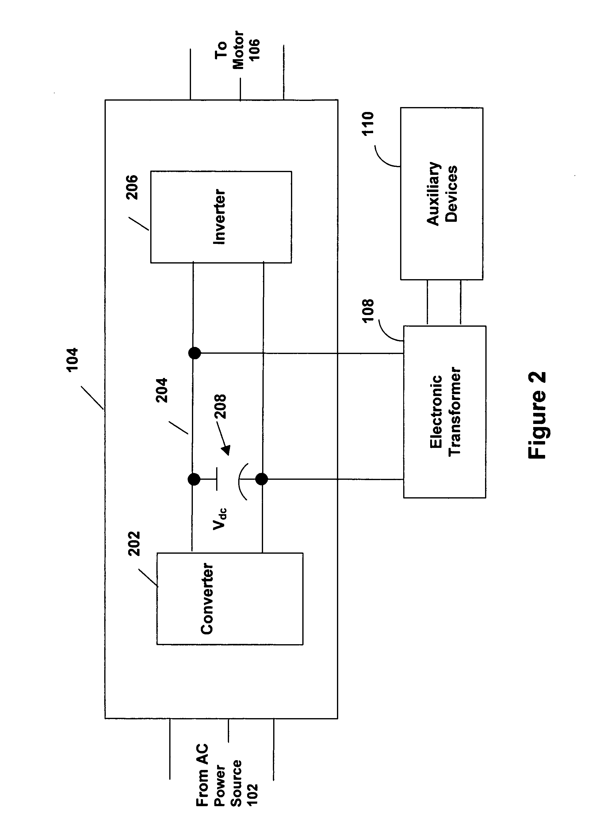
[0026]FIGS. 1 and 2 illustrate generally the system configuration of the present invention. An electronic transformer 108 is configured to provide AC power from the DC link 204 of a variable speed drive (VSD) 104. The electronic transformer 108 has at least four semiconductor switches and converts the DC link voltage to a fixed voltage, fixed frequency AC output. An AC power source 102 supplies AC power to the VSD 104, which in turn, supplies AC power to a motor 106. In another embodiment of the present invention, the VSD 104 can power more than one motor 106. The motor 106 is preferably used to drive a corresponding compressor of a refrigeration or chiller system. The VSD 104 also supplies power to an electronic transformer 108 from the DC link 204. The electronic transformer 108 converts the DC power from the DC link 204 to a fixed voltage and frequency AC control power source for various auxiliary devices 110, e.g. a control panel, contactors, relays, pumps and fans, that are com...


PUM


Abstract

In a chiller system, an electronic control transformer is powered by the DC link of a variable speed drive that drives a compressor motor. The electronic control transformer converts the DC voltage to a constant 120 VAC at 60 Hz, for providing power to auxiliary electrical devices associated with the chiller system. The electronic transformer includes four semiconductor switches to convert the DC voltage to AC. The energy stored in the compressor motor is transferred to the DC link of the VSD during an input voltage sag. The electronic control transformer maintains the control voltage and prevents the system auxiliary loads from dropping out during a voltage sag. The chiller system is able to ride through the input voltage sag or interruption. A boost converter may be provided at the input of the VSD to increase ride through capability.

Description

BACKGROUND OF THE INVENTION [0001] The present invention relates generally to an electronic transformer for supplying control voltage. More specifically, the present invention relates to an electronic control transformer powered by the DC link of a variable speed drive for a chiller system. [0002] In the past, the motors for driving compressors in chiller systems were designed to operate from standard line (main) voltages and frequencies that were available from the power distribution system of the facility where the motor was being operated. The use of line voltages and frequencies typically limited the options for modulating the capacity of the compressors to less efficient mechanical devices such as inlet guide vanes and slide valves, as a result of the motor being limited to one operating speed that was based on the input frequency to the motor. In addition, if the operating speed of the motor was not equal to the desired operating speed of the compressor, a “step up,” or “step ...

Claims


Application Information

Patent Timeline
IPC IPC(8): F25B49/00F25B1/00
CPCF25B49/025Y02B30/741F25B2600/021Y02B30/70F25B1/00H02M7/48
Inventor COSAN, MUHAMMETSCHNETZKA, HAROLD R.
Owner YORK INT
Learn More