Negative pressure tabletop dust collecting machine

a negative pressure technology, applied in cleaning equipments, manufacturing tools, separation processes, etc., can solve the problems of large volume, complicated structure, and large volume of the dust collection unit of the conventional tabletop dust collection machine, so as to simplify the structure, reduce the volume, and reduce the volume

Inactive Publication Date: 2007-07-05
SAN FORD MACHINERY
View PDF9 Cites 12 Cited by
  • Summary
  • Abstract
  • Description
  • Claims
  • Application Information

AI Technical Summary

Benefits of technology

[0006] The objective of the invention is to offer a negative pressure table-top dust collecting machine, which includes a machine box with an interior space, an operation faceplate assembled on the topside of the machine box and bored with numerous wind-sucking vents, a fixing base positioned in the interior space of the machine box, a dust-collecting unit assembled on the fixing base and provided with dust-collecting bags, and a blower installed in the interior space of the machine box. When the blower is started to operate, the air in the interior of the machine box can be pumped out of the machine box, letting the interior of the machine box produce negative pressure and each wind-sucking vent of the operation faceplate produce a vacuum suction force through the dust-collecting bag and the fixing base for sucking in the dust produced during processing and collecting it in the dust-collecting bag. In this invention, the blower and the dust-collecting unit are installed in the interior of the machine box so it is needless to additionally provide connecting pipes, greatly. diminishing the volume, taking less space, simplify its structure and convenient to be moved around.

Problems solved by technology

However, the dust-collecting unit of the conventional tabletop dust-collecting machine is exposed outside, large in volume and taking much space.
In addition, wind-sucking pipes have to be additionally disposed between the blower and the machine table as well as the wind cover, and the bottom base has to be provided for assembling the blower and the wind cover thereon, thus complicating the structure, increasing producing cost and inconvenient to be moved around.

Method used


Image

  • Negative pressure tabletop dust collecting machine
  • Negative pressure tabletop dust collecting machine
  • Negative pressure tabletop dust collecting machine

Examples


Embodiment Construction

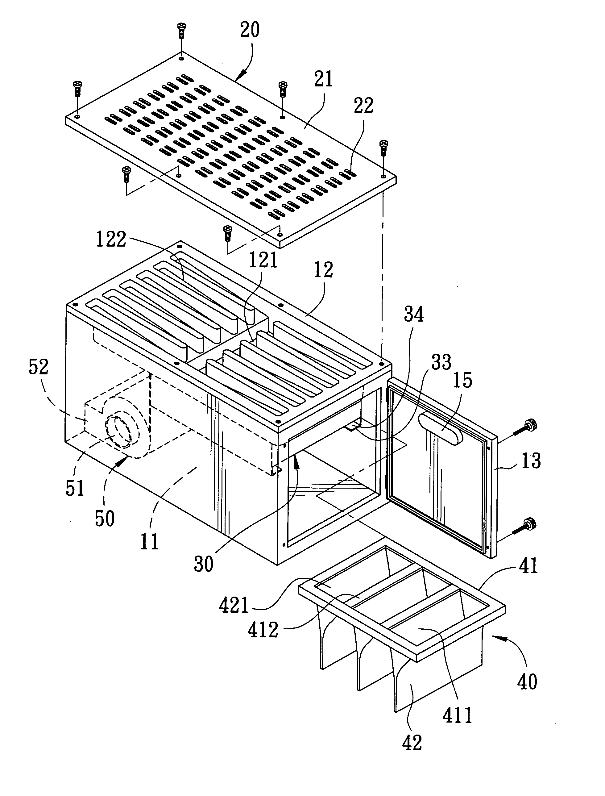
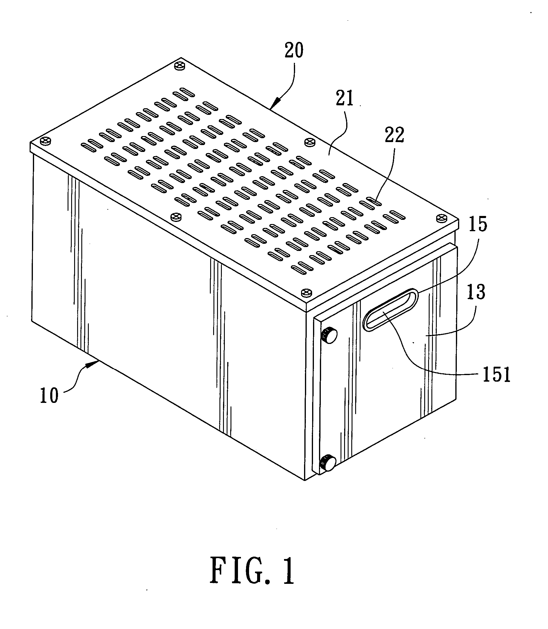
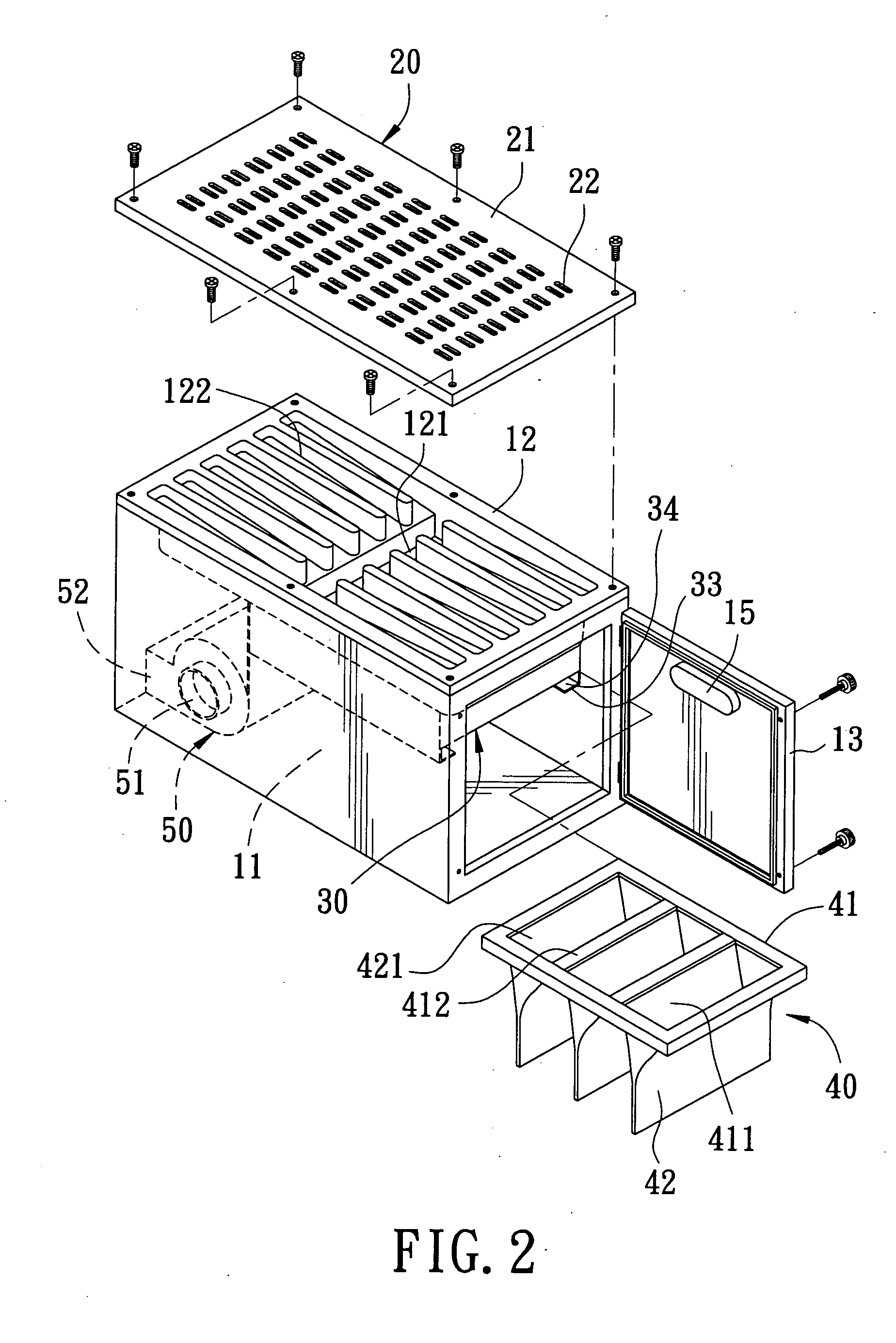
[0012] A preferred embodiment of a negative pressure table-top dust collecting machine in the present invention, as shown in FIGS. 1, 2 and 3, includes a machine box 10, an operation faceplate 20, a fixing base 30, a dust collecting unit 40 and a blower 50 combined together.

[0013] The machine box 10 is formed with a closed interior space 11 and has the intermediate portion of its top wall 12 bored with a vertical wind vent 121 and has the upper left and right side of the top wall 12 respectively and symmetrically bored with a plurality of recessed guide grooves 122, which have their bottoms slanting downward toward the wind vent 121. Further, the machine box 10 has its right side wall pivotally assembled with a door plate 13 able to be opened and closed and has its left side all bored with a wind-exhausting opening 14 near the lower side. In addition, the machine box 10 has its left wall and its doorplate 13 respectively provided near the upper side with a grasping member 15 with a...


PUM

PropertyMeasurementUnit
pressureaaaaaaaaaa
vacuum suction forceaaaaaaaaaa
volumeaaaaaaaaaa

Abstract

A negative pressure table-top dust collecting machine includes a machine box formed with an interior space, an operation faceplate assembled on the machine box and bored with numerous wind-sucking vents, a fixing base disposed in the interior space of the machine box, a dust collecting unit fitted with the fixing base and provided with dust collecting bags, and a blower positioned in the interior space of the machine box. When the blower is started to operate, the air in the interior of the machine box is pumped out of the machine box, letting the interior of the machine box produce negative pressure. Simultaneously, through the dust collecting bags and the fixing base, each wind-sucking vent of the operation faceplate will produce a vacuum suction force to suck the dust produced during processing into the dust collecting bags to be gathered.

Description

BACKGROUND OF THE INVENTION [0001] 1. Field of the Invention [0002] This invention relates to a negative pressure tabletop dust-collecting machine, particularly to one taking less space and convenient to be moved around. [0003] 2. Description of the Prior Art [0004] A conventional tabletop dust-collecting machine includes a support frame having its topside assembled with a machine table provided thereon with a work faceplate with wind-sucking vents. The machine table is connected with a wind-sucking pipe connected with a dust-collecting unit, which is composed of a blower connected with the wind-sucking pipe, a wind cover connected with the blower, a dust-collecting bag assembled with the wind cover and a bottom base for assembling the blower and wind cover thereon. When the blower is started to operate, each wind-sucking vent of the work faceplate will produce a vacuum suction force through the wind-sucking pipe and the machine table for sucking in the dust produced during processi...

Claims


Application Information

Patent Timeline
Patent Type & Authority Applications(United States)
IPC IPC(8): A47L5/38
CPCA47L7/0047B23Q11/0046B08B15/00B01D46/02
Inventor CHENG, CHIEH-YUAN
Owner SAN FORD MACHINERY
Why Eureka
Try Eureka