Power transmission chain, manufacture method thereof and power transmission assembly

Inactive Publication Date: 2007-06-28
JTEKT CORP
View PDF5 Cites 11 Cited by
  • Summary
  • Abstract
  • Description
  • Claims
  • Application Information

AI Technical Summary

Benefits of technology

[0007] According to the power transmission chain of the aforementioned arrangement, the plural link plates are provided with the spacing therebetween so that these link plates are prevented from contacting each other to produce the friction drag when the chain is flexed. Thus, the chain may be reduced in the flexion torque. Accordingly, the power transmission chain is capable of suppressing the decrease of power transmission efficiency.
[0021] In this case, the power transmission assembly is adapted to suppress the decrease of power transmission efficiency because the aforesaid power transmission chain is employed. Furthermore, in a case where the spacing is provided between a respective pair of link plates adjoining each other in the chain widthwise direction, for example, the pin is allowed to move in the chain widthwise direction. Therefore, if misalignment occurs due to deviation between the relative positions of the first pulley and the second pulley, the pin may be moved (skewed) in the chain widthwise direction to accommodate the misalignment. As a result, the pin is prevented from pressing its corner against the corresponding sheave surface to cause abnormal wear of the pin and the sheave surface. Thus, the assembly may be dramatically increased in service life.

Problems solved by technology

The chain assembled in this state is detrimentally increased in flexion torque due to friction drag produced on contact surface between the adjoining link plates of the chain being flexed.
Hence, the chain may suffer decreased power transmission efficiency.

Method used


Image

  • Power transmission chain, manufacture method thereof and power transmission assembly
  • Power transmission chain, manufacture method thereof and power transmission assembly
  • Power transmission chain, manufacture method thereof and power transmission assembly

Examples


first embodiment

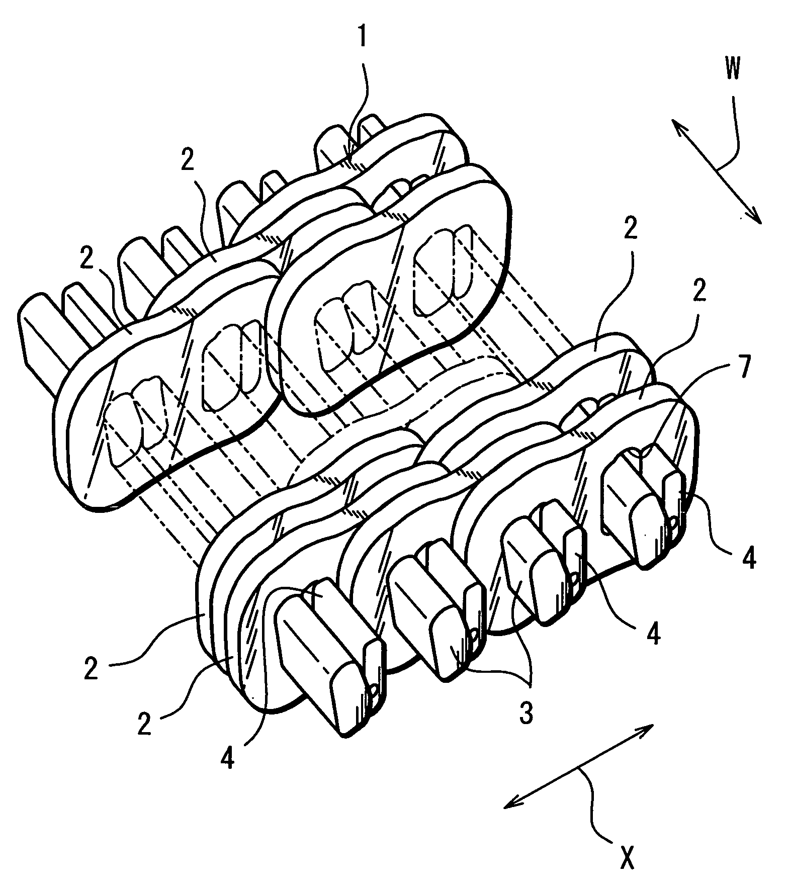
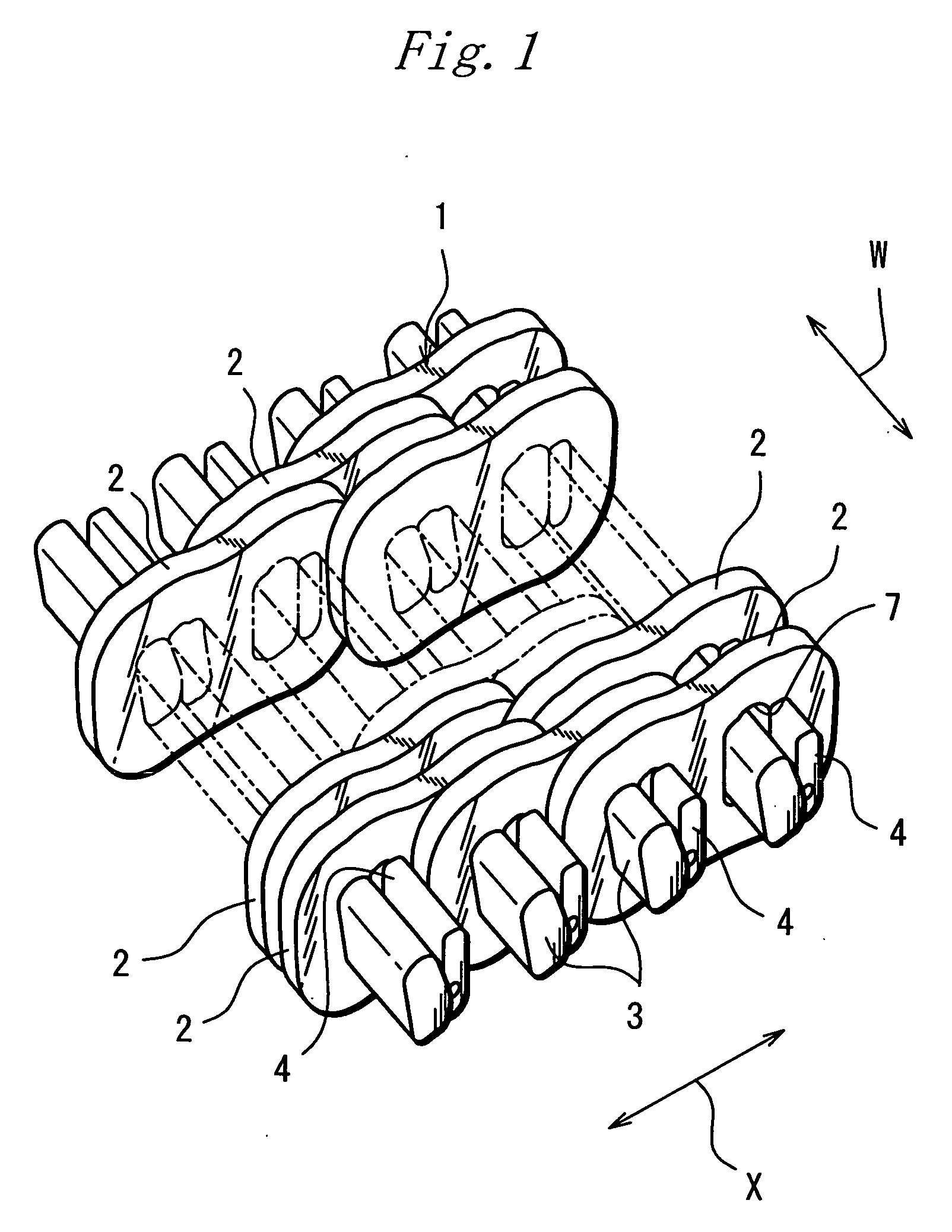
[0035] Preferred embodiments of the invention will be described with reference to the accompanying drawings. FIG. 1 is a perspective view schematically showing an arrangement of an essential part of a power transmission chain (hereinafter, also referred to simply as “chain”) for use in chain-type continuously variable transmission according to the invention. Referring to FIG. 1, a chain 1 includes: a plurality of link plates 2 arranged in a chain advancing (driving) direction X and in a chain widthwise direction W; a plurality of pins 3 for interconnecting these link plates 2; and a plurality of strips 4 slightly shorter than the pins 3.

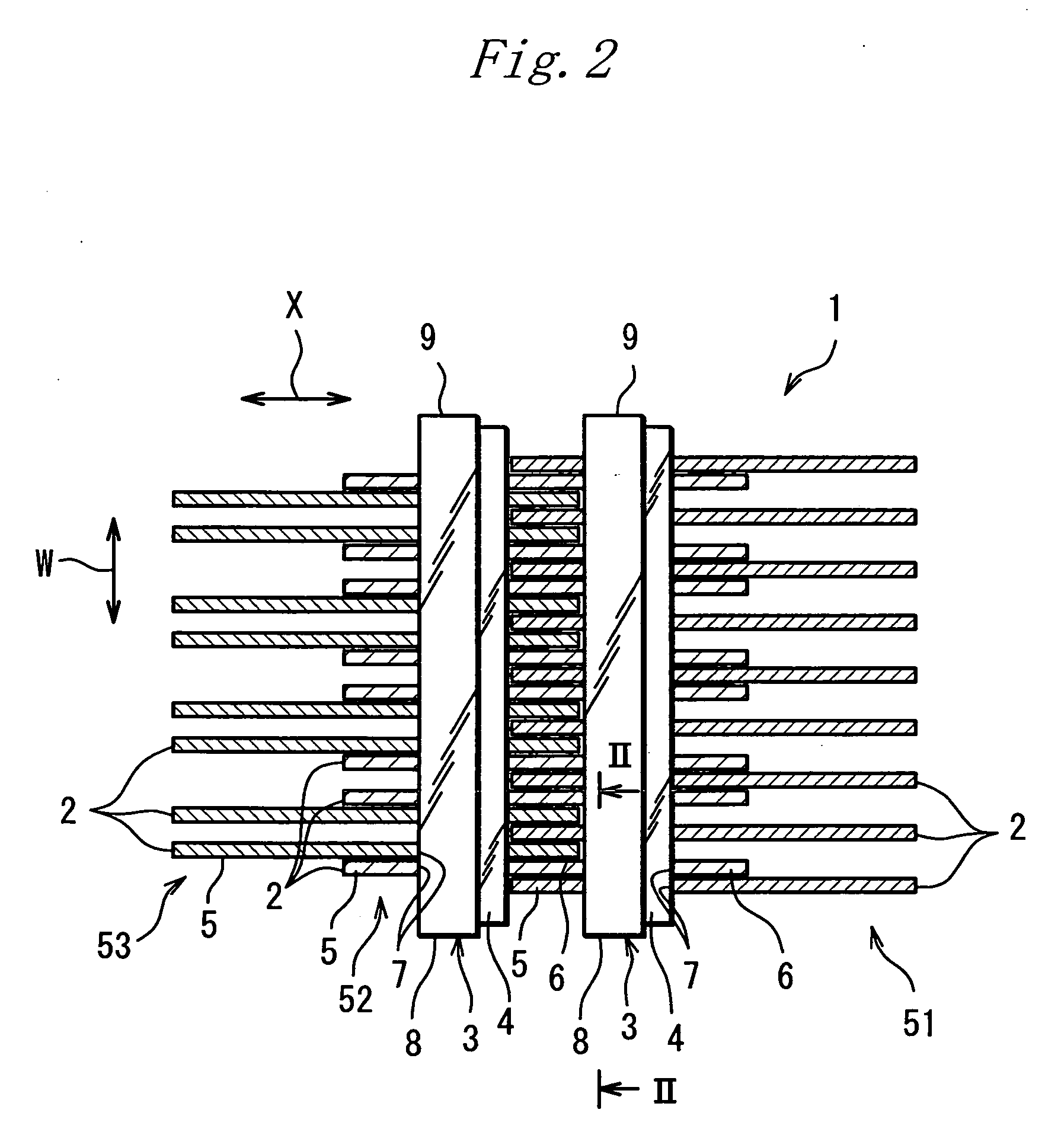
[0036]FIG. 2 is sectional view of the essential part of the chain 1 shown in FIG. 1. The figure shows three groups of link plates, each group including plural link plates located at the same position with respect to the chain advancing direction X. Specifically, the figure shows a first link-plate group 51, a second link-plate group 52 and a third li...

third embodiment

[0084]FIG. 10 is a perspective view schematically showing an arrangement of an essential part of a chain-type continuously variable transmission (hereinafter, also referred to simply as “continuously variable transmission”) according to the invention. The continuously variable transmission is a power transmission assembly. The continuously variable transmission of the embodiment is mounted in a vehicle such as automotive vehicles and includes: a drive pulley 70 formed from a metal (steel for machine structural use, etc.) and serving as a first pulley; a driven pulley 80 formed from a metal (steel for machine structural use, etc.) and serving as a second pulley; and an endless chain 1 entrained between these pulleys 70, 80. FIG. 10 depicts the chain 1 partly in section for the sake of clarity.

[0085]FIG. 11 is a fragmentary enlarged sectional view of the drive pulley 70 (driven pulley 80) and the chain 1 of the chain-type continuously variable transmission shown in FIG. 10. Referring ...


PUM


Abstract

A power transmission chain of the invention includes: plural link plates individually including through-holes and arranged in a chain advancing direction and a chain widthwise direction and with predetermined spacing; and plural pins inserted through the through-holes for flexibly interconnecting the link plates. Since the link plates are arranged in the chain widthwise direction with the predetermined spacing, a respective pair of adjoining link plates are prevented from coming into friction contact with each other during the operation of the power transmission chain. Hence, the power transmission chain may be prevented from suffering the decrease of power transmission efficiency.

Description

TECHNICAL FIELD [0001] The present invention relates to a power transmission chain for use in a continuously variable transmission for vehicles and a manufacture method thereof, as well as to a power transmission assembly using this power transmission chain. BACKGROUND ART [0002] One type of continuously variable transmission (CVT) for automotive vehicles includes, for example: a drive pulley disposed on an engine side; a driven pulley disposed on a drive-wheel side; and an endless power transmission chain entrained between these pulleys and including a plurality of link plates and a plurality of pins interconnecting these link plates. Such a continuously variable transmission of a so-called chain type transmits power by way of traction, which is produced by holding conical sheave surfaces of the individual pulleys in contact with a part of a chain component member, such as end faces of the pins of the chain, as allowing for a minor (micro) sliding movement of the chain component me...

Claims


Application Information

Patent Timeline
IPC IPC(8): F16G13/04F16G5/16F16G5/18
CPCF16G5/18F16G13/00
Inventor YASUHARA, SHINJIKAMAMOTO, SHIGEOFUKUI, NOBUKIOKUMOTO, MASAFUMIFUSE, MASARU
Owner JTEKT CORP
Why Eureka
Try Eureka