
Case structure for electronic device

a technology for electronic devices and casings, applied in the direction of electrical apparatus casings/cabinets/drawers, coupling device connections, gaseous cathodes, etc., can solve the problems of high manufacturing cost and time-consuming manufacturing process, and achieve the effect of saving human resources, reducing molding costs, and saving a large amount of time needed

Inactive Publication Date: 2007-06-28
INVENTEC CORP
View PDF9 Cites 1 Cited by
  • Summary
  • Abstract
  • Description
  • Claims
  • Application Information

AI Technical Summary

Benefits of technology

[0004] According to the above defects, a primary objective of the present invention is to provide a case structure for an electronic device which only needs to be partially changed to meet a new design, thereby decreasing the manufacturing cost and shortening the manufacturing time.
[0011] Therefore, the present invention could provide different sizes of electronic devices by changing the size of the side piece while keeping the main body unchanged, thereby reducing molding cost for developing new electronic devices, saving a large amount of time needed to design, test and modify cases as well as saving human resources and reducing the manufacturing cost.

Problems solved by technology

For a newly developed type of notebook computer, a new case structure usually needs to be designed and a new molding process is needed, which results in high manufacturing cost and a time-consuming manufacturing process.

Method used


Image

  • Case structure for electronic device
  • Case structure for electronic device
  • Case structure for electronic device

Examples


Embodiment Construction

[0018] Hereunder, embodiments of the present invention will be described in detail with reference to the accompanying drawings.

[0019] In the following embodiments, the electronic device of the present invention refers to a notebook computer, but it is not limited thereto. Those skilled in the art will understand that the electronic device could also be a PDA (Personal Digital Assistant), a game player, a palmtop computer or a mobile phone.

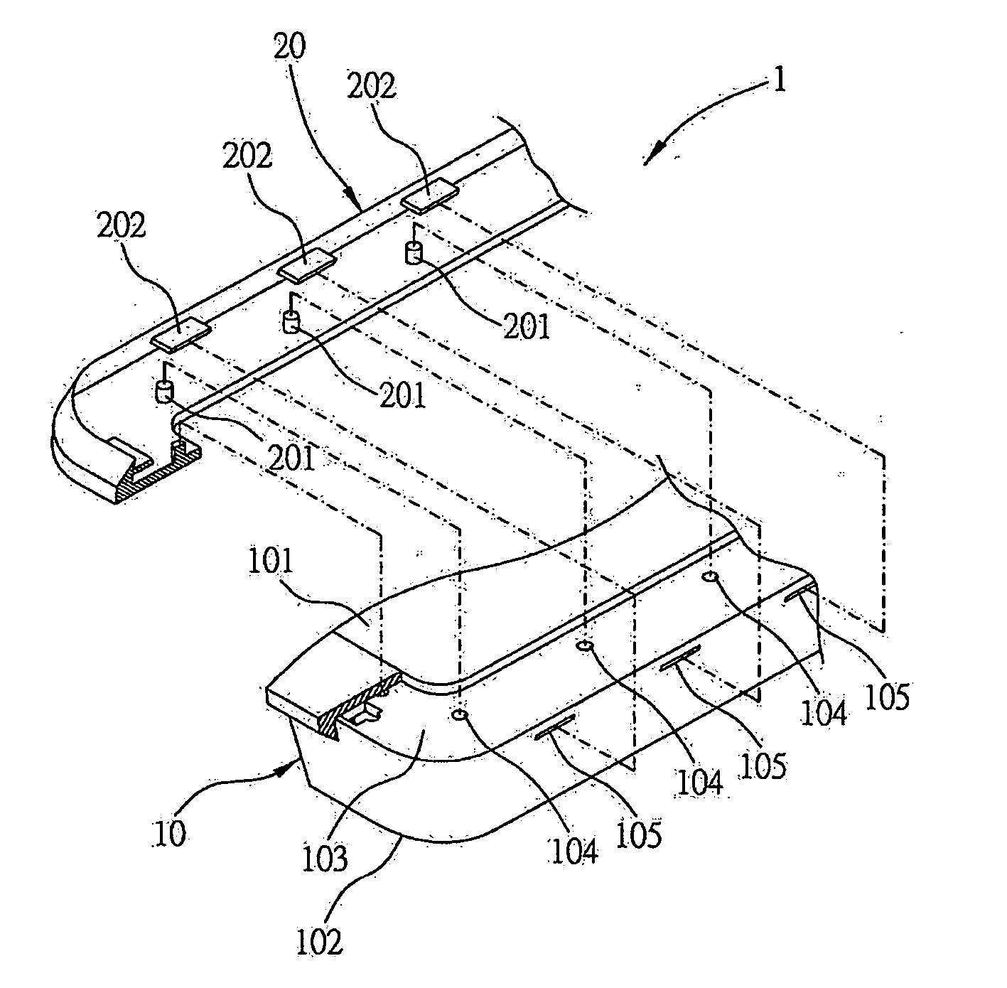
[0020] Please referring to FIG. 1, which shows a partial three-dimensional perspective diagram of a case structure 1 of the present invention. The case structure 1 according to a first embodiment of the present invention includes a main body 10 provided with an upper case 101 and a lower case 102 and a side piece 20 provided with a plurality of tenons 201 and hooks 202.

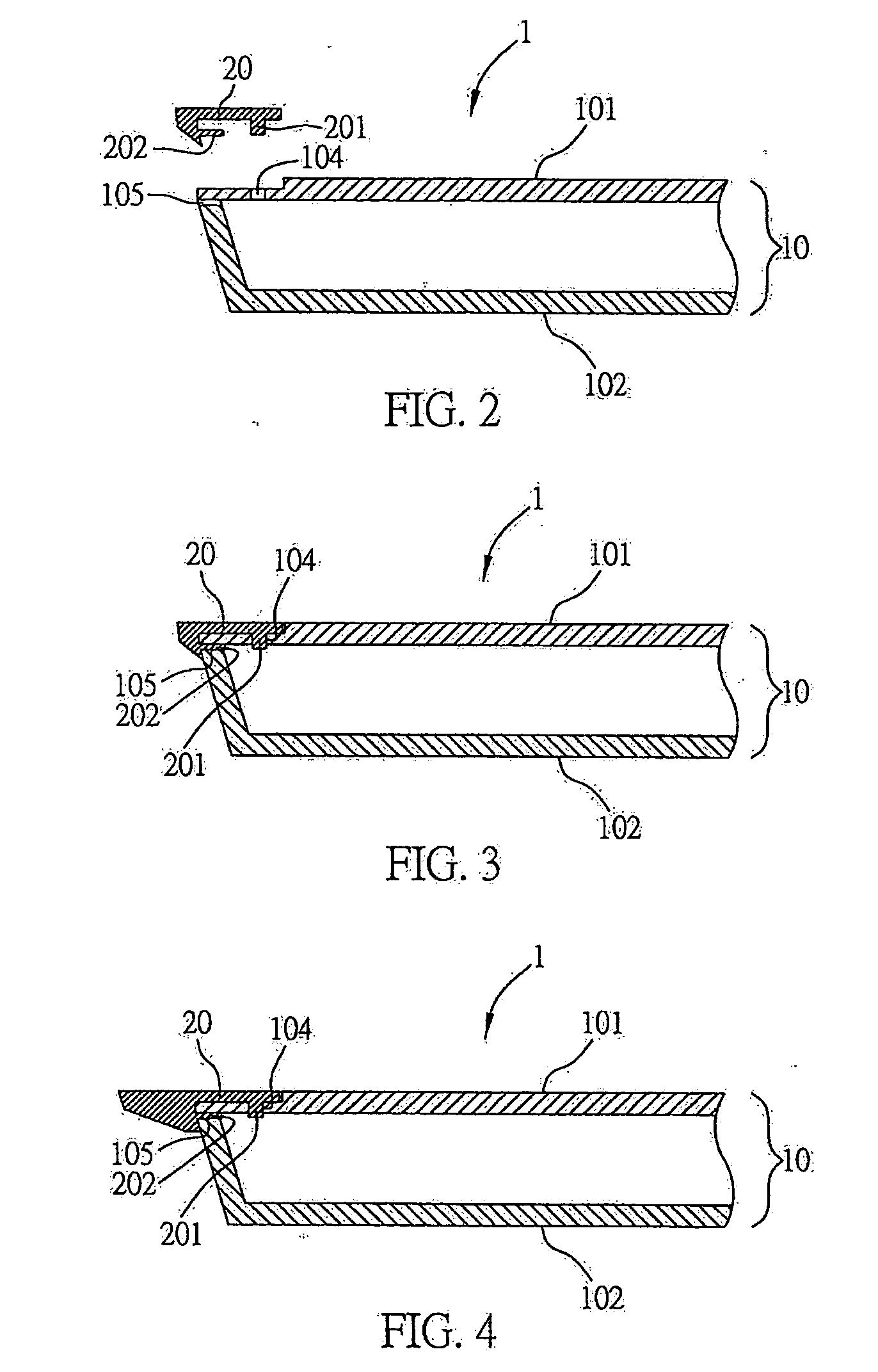
[0021] Referring to FIGS. 1 and 2, the upper case 101 is longer than the lower case 102, thereby the cross section of the main body 10 having trapezoid shape. A recess 103 is form...


PUM


Abstract

A case structure for an electronic device of the present invention at least includes a main body and at least one side piece detachably mounted to at least one side of the main body such that different sizes of case structures could be manufactured only by changing the size of the side piece while keeping the main body unchanged, thereby reducing molding cost for developing new electronic devices, saving a large amount of time needed to design, test and modify cases as well as saving human resources and reducing the manufacturing cost.

Description

FIELD OF THE INVENTION [0001] The present invention relates to case structures for electronic devices, and more particularly to a case structure for receiving main components of an electronic device. BACKGROUND OF THE INVENTION [0002] Currently, notebook computers on the market are usually provided with a 14.1- or 15-inch display. However, with the trend towards both portability and better visual effect, notebook computer manufacturers are developing diversified types of notebook computers to meet different demands of people. For a newly developed type of notebook computer, a new case structure usually needs to be designed and a new molding process is needed, which results in high manufacturing cost and a time-consuming manufacturing process. [0003] Accordingly, there is a need to develop a case structure for an electronic device which only needs to be partially changed to meet a new design. SUMMARY OF THE INVENTION [0004] According to the above defects, a primary objective of the p...

Claims


Application Information

Patent Timeline
Patent Type & Authority Applications(United States)
IPC IPC(8): H02G3/08
CPCH05K5/0013
Inventor ZHANG, XIN-YULIN, TIEN-CHANG
Owner INVENTEC CORP
Learn More