
Handle for hand-held power tool

Active Publication Date: 2007-06-28
HILTI AG
View PDF10 Cites 6 Cited by
  • Summary
  • Abstract
  • Description
  • Claims
  • Application Information

AI Technical Summary

Benefits of technology

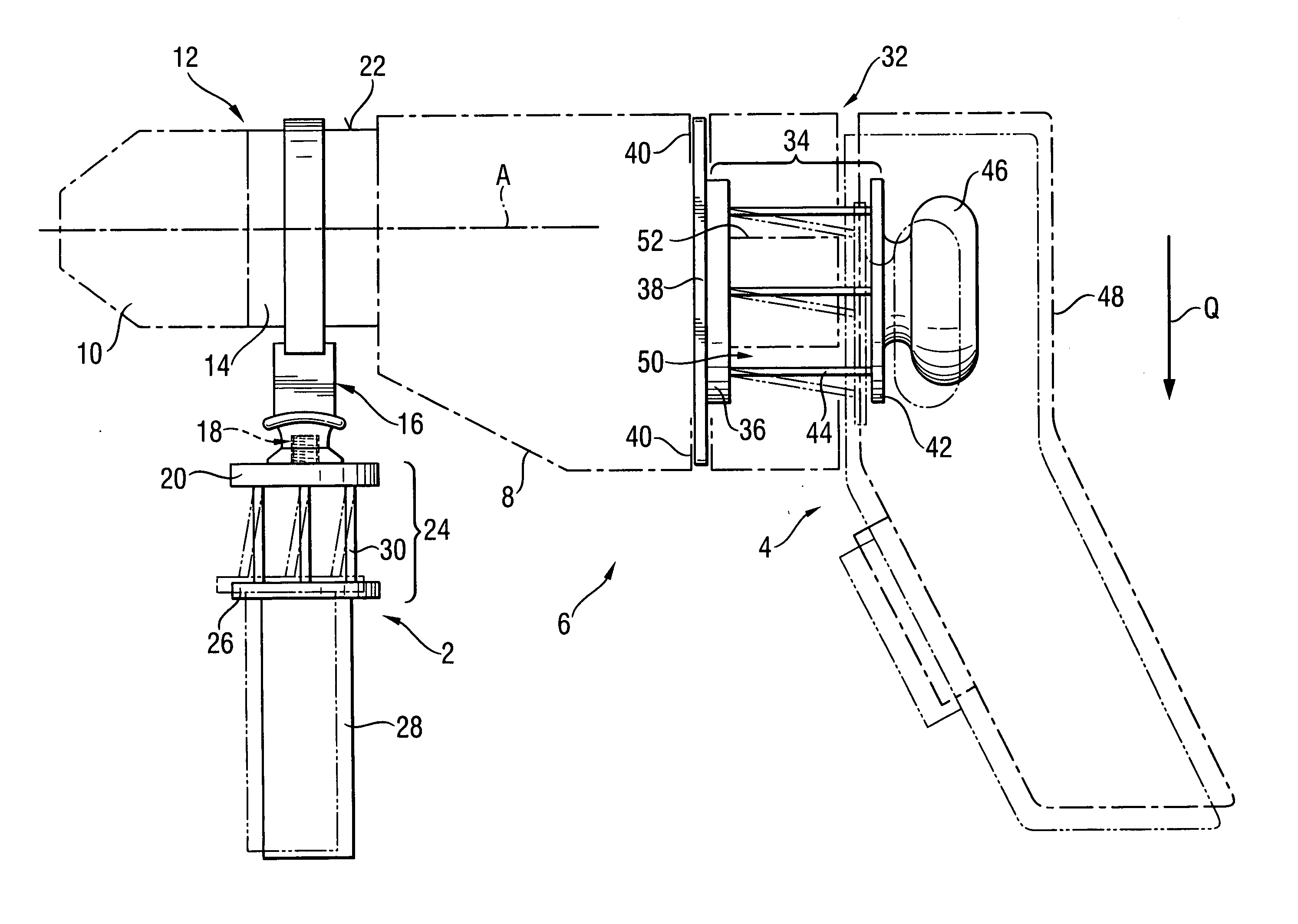
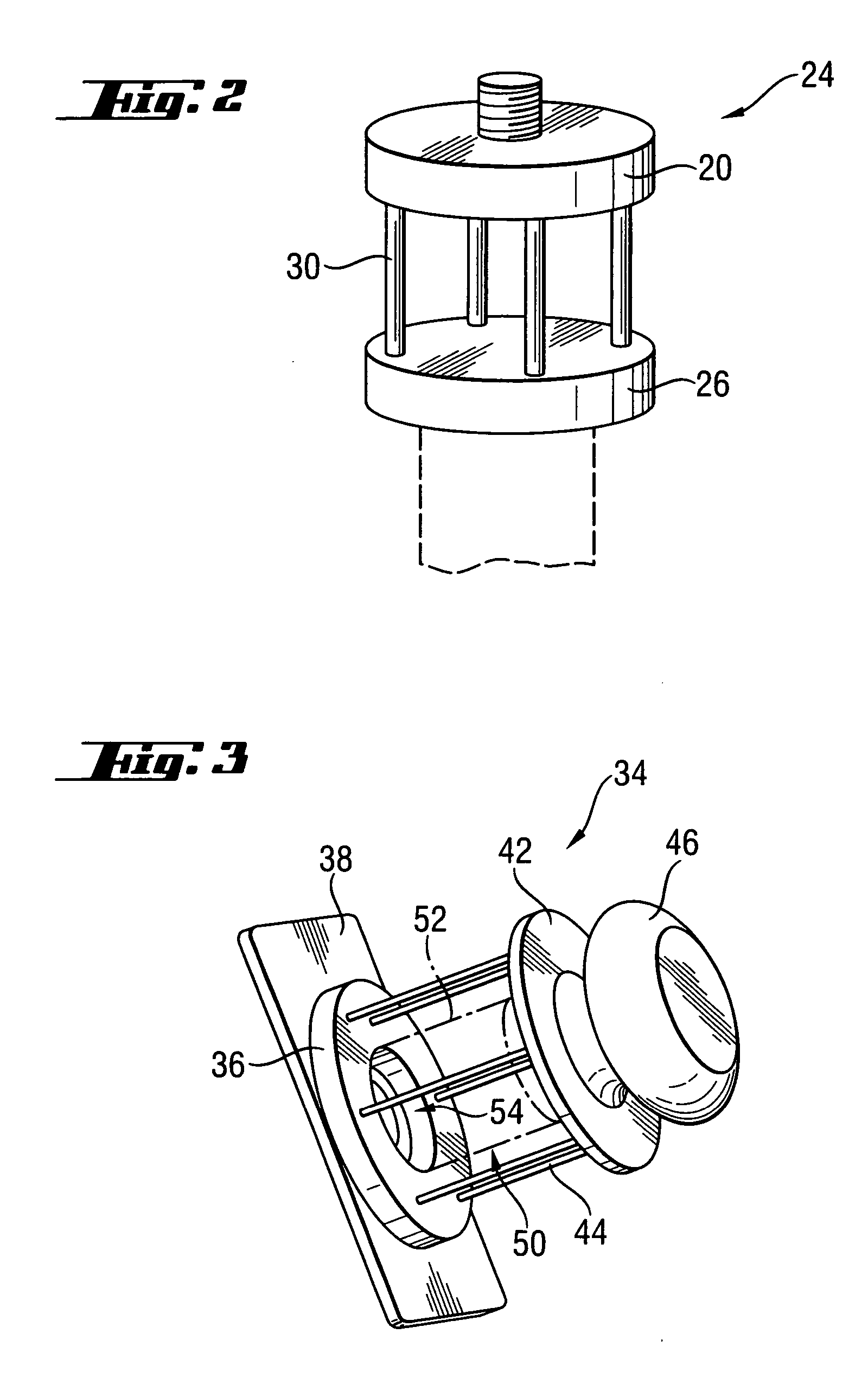
[0010] With the decoupling elements extending parallel to each other, the elements are deflected parallel to each other. The decoupling elements provide for a particularly constructing simple decoupling of the grip element from the support member, with the deflectable, parallel to each other, decoupling elements simultaneously insuring a position-stable guidance of the grip element. The grip element retains the same orientation during its positive movement with respect to the support member or the hand-held power tool by the decoupling elements. In this way, a stable guidance of the power tool at a substantially reduced transmission of vibrations to the grip element is insured. In addition, with the inventive decoupling elements, the decoupling device can be formed very compact, so that it can be easily integrated in the hand-held power-tool or the auxiliary handle.
[0011] During the operation of the power tool, no obstructions, which may be caused, e.g., by tilting of the decoupling device, arise. All in all, a comfortable handling has been achieved with low manufacturing costs.
[0012] Advantageously, the pin-shaped decoupling elements are formed of a wire-shaped material, which particularly reduces the manufacturing costs.
[0015] When the handle is used as a side handle, there are provided precisely four decoupling elements. With this number of decoupling elements, a particular good vibration decoupling simultaneously with relatively stable guidance of the grip element relative to the support member are achieved. This provides a side handle that can be handled particularly comfortably.
[0018] In this way the space between the decoupling elements also can be used, which decreases the space occupied by the hand-held power tool.

Problems solved by technology

The drawback of the handle disclosed in the above mentioned German Publication consists in that the support unit for the translational guidance of the grip element is very expensive and rather bulky.

Method used


Image

  • Handle for hand-held power tool
  • Handle for hand-held power tool
  • Handle for hand-held power tool

Examples


Embodiment Construction

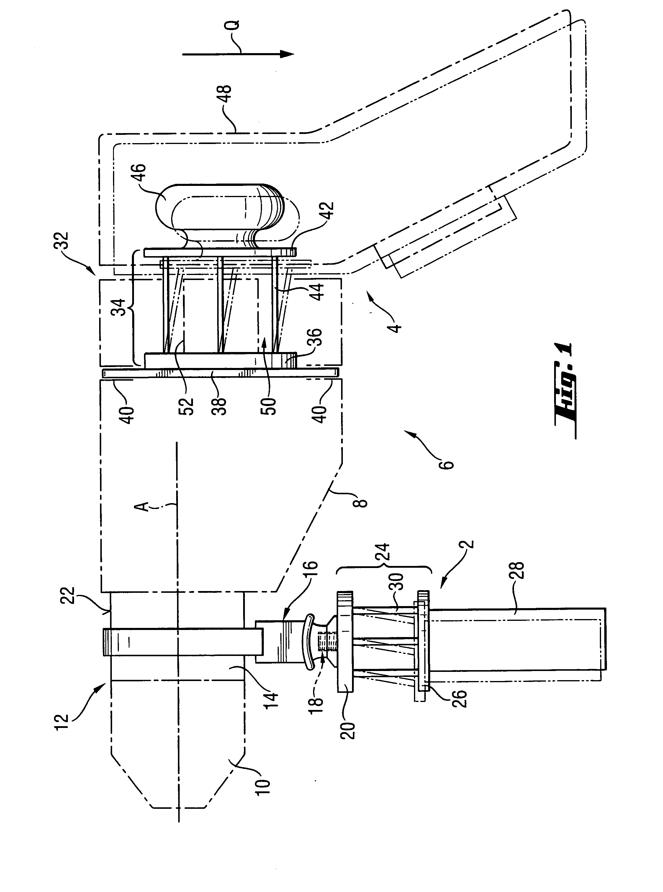
[0025]FIG. 1 shows a main handle 4 of a hand-held power tool 6 in form of power drill or chisel tool and a side handle-forming additional handle 2 used only when needed. The additional handle 2 and the main handle 4 can also be used on a scroll saw or a grinder, in particular, angle grinder.

[0026] The hand-held power tool 6 has a housing 8 that extends substantially along longitudinal axis A. At its first end 12 adjacent to the chuck 10 for receiving a working tool, the housing 8 has a neck 14 on which the additional hand 2 is secured. To this end, the additional handle 2 has first attachment means 16 in form of a locking device that is connected by screw means 18 with a plate-shaped support member 20. The first attachment means 16 are releasably tightened on a cylindrical surface of the housing neck 14 that serves as first counter-attachment means 22.

[0027] The plate-shaped support member 20 forms a part, which is fixedly connected with the housing 8, of a first decoupling device...


PUM


Abstract

A handle (2; 4) for a hand-held power tool (6) includes a support member (20; 36) for securing the handle grip element (28; 48) to the hand-held power tool (6), and a decoupling device (24; 34) for at least partially vibration-decoupling of the grip element (28; 48) from the support member (20, 36) and including at least three, spaced from each other and extending parallel to each other pin-shaped decoupling elements (30; 44) for connecting the grip element (28; 48) with the support member (20; 36) and for guiding the grip element (28; 48) relative the support member (20; 36), without a position stability of the grip element being affected.

Description

BACKGROUND OF THE INVENTION [0001] 1. Field of the Invention [0002] The present invention relates to a handle for hand-held power tools such as, e.g., power drill or chisel power tool having a handle that a user of a power tool can comfortably grasp. The handle has a support member to be permanently or releasably secured on the power tool. The handle grip element and the support member are connected with a decoupling device for at least partially vibration-decoupling of the grip element from the support member and for guiding the grip element relative to the support member without the position stability of the grip member being affected, i.e., the grip element retains the same orientation upon being displaced relative to the support member. The present invention also relates to a hand-held power tool with such a handle. [0003] 2. Description of the Prior Art [0004] A handle of the type discussed above has an advantage that consists in that the decoupling takes place in one predeterm...

Claims


Application Information

Patent Timeline
IPC IPC(8): B25G3/32
CPCB25D17/043B25F5/006F16F3/023F16F15/02Y10T16/48F16F2236/027Y10T16/498Y10T16/469Y10T16/4713F16F2230/0052
Inventor PFEIFFER, RALFHOLZMEIER, GEORG
Owner HILTI AG
Learn More