Telescopic vacuum cleaner suction tube with an interlocking element in the form of a bow spring

Inactive Publication Date: 2007-06-28
FISCHER ROHRTECHN
View PDF16 Cites 1 Cited by
  • Summary
  • Abstract
  • Description
  • Claims
  • Application Information

AI Technical Summary

Benefits of technology

[0006]Based on this state of the art, the invention aims to develop a telescopic vacuum cleaner suction tube of the initially cited type that significantly lowers the manufacturing and assembly expenditures of the interlocking device and ensures that the tubes are always securely interlocked and able to withstand shock-like compressive forces, namely while simultaneously providing for an ergonomic handling.
[0013]If the bow spring has a rectangular cross section, the corresponding snap-in depressions that have a similar, adapted geometry and are flatly embossed in the inner tube are so minimal that their flow cross section and therefore the flow resistance within the inner tube is substantially lowered in comparison with the state of the art, in which semicircular snap-in depressions are used. The flow resistance is essentially defined by the known antitwisting mechanism that is also not required in this case. The entire interlocking device only consists of two parts, namely a bow spring and an actuating element in the form of a push-button or a slide, such that the manufacturing and assembly expenditures are significantly lowered.
[0014]When the free ends of the bow spring are spread apart by the actuating element, the about diametrically opposite snap-in element is surprisingly lifted out of the snap-in depression, wherein this was not expected at all when the opposite region is spread apart. This may be the reason why no person skilled in the art has attempted to realize such a function in a corresponding interlocking device prior to the application date. It was also surprisingly determined that the interlocking device that merely consists of the bow spring and the actuating element makes it possible to always ensure that the tubes are reliably interlocked and that the interlocking device can be quickly disengaged in order to initiate a telescoping process.
[0019]According to a second advantageous embodiment of the invention, the actuating element consists of a slide that is arranged on the outer tube such that it can be moved parallel to the direction of the longitudinal symmetry axis. This slide features two cone surfaces that adjoin the ramps formed by the bent ends of the bow spring in a paired fashion and are connected to one another similar to an hourglass at their opposite pointed regions such that the movement of the slide in either direction parallel to the longitudinal symmetry axis of the tube causes the bow spring to be spread apart. This makes it possible to ergonomically pull the slide in direction of the handle, e.g., in order to pull apart the telescopic tubes, and to press the slide in the direction of the nozzle part when the tubes are pushed into one another, i.e., the movement of the slide in one or the other direction is coordinated with the corresponding telescoping process.
[0024]When using a bow spring with circular cross section according to the state of the art and an actuating element in the form of a slide, said slide is advantageously realized in the form of a sliding sleeve that completely encompasses the outer tube and features a safety projection on its inner surface that lies nearest the snap-in element, wherein said safety projection engages underneath the snap-in element in exactly its central region in the engaged position. This safety projection ensures that shock-like impulses exerted upon one end or both ends of the tubes do not result in the tubes being undesirably pushed into one another—in contrast to the state of the art. The snap-in element can only disengage from the snap-in depression once the slide is displaced relative to the snap-in element in one of the two possible directions in the central region of the safety projection. Otherwise, this disengagement is prevented by the safety projection.
[0026]If the slide is designed with guide grooves for spreading apart the ends of the bow spring, the curved paths of these guide grooves are adapted to the geometry of the safety projection in such a way that the process of spreading apart the ends of the bow spring can only begin after a short linear displacement within a straight section of the curved path. This defined progression of the curved paths makes it possible to preclude any jamming between the safety projection and the snap-in element when the interlocked tubes are disengaged.

Problems solved by technology

When shock-like compressive forces are exerted upon the ends of the outer and / or inner tube, the snap-in element may slide upward and out of the snap-in depression on an oblique plane against the force of the leaf spring, wherein the snap-in element is disengaged and an undesirable telescopic adjustment takes place.
The leaf spring that presses the snap-in element back into the snap-in depression not only increases the manufacturing and assembly expenditures, but also requires a sleeve-like handle around the outer and inner tubes in order to accommodate and simultaneously secure the leaf spring such that not only the assembly expenditure is increased, but also the manufacturing expenditure.

Method used


Image

  • Telescopic vacuum cleaner suction tube with an interlocking element in the form of a bow spring
  • Telescopic vacuum cleaner suction tube with an interlocking element in the form of a bow spring
  • Telescopic vacuum cleaner suction tube with an interlocking element in the form of a bow spring

Examples


Embodiment Construction

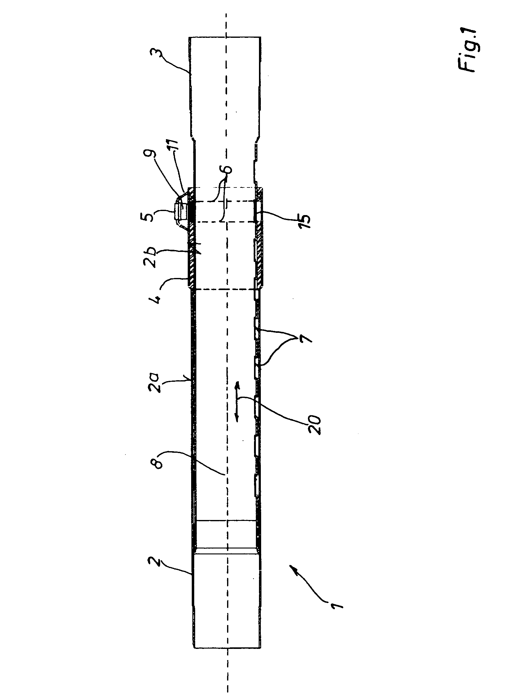
[0076]In all figures, the telescopic vacuum cleaner suction tube is always identified by the reference symbol 1, the outer tube is identified by the reference symbol 2, its inner tube is identified by the reference symbol 3, the guide sleeve is identified by the reference symbol 4, the actuating element is identified by the reference symbol 5, the bow spring is identified by the reference symbol 6, the snap-in depressions are identified by the reference symbol 7 and the longitudinal symmetry axis is identified the reference symbol 8.

[0077]The individual embodiments can essentially be distinguished by the cross-sectional shape of the bow spring 6 as well as the design of the actuating element 5 in the form of either a push-button 9 or a slide 10.

[0078]According to a first embodiment that is shown in FIGS. 1 to 8, the actuating element 5 is realized in the form of a push-button 9. FIGS. 2 and 3 also show that the bow spring 6 in FIGS. 6 to 8 is realized with the cross-sectional shape ...


PUM


Abstract

The invention pertains to a telescopic vacuum cleaner suction tube (1) with an outer tube (2), an inner tube (3) with snap-in depressions (7) that is telescopically arranged in the outer tube, an antitwisting mechanism (4d; 16) and an interlocking device with a snap-in element (15) that is disengaged from a snap-in depression (7) by an actuating element (5) situated about diametrically opposite thereof, wherein the interlocking device consists of a bow spring (6) that positively encompasses at least the inner tube (3) and once again engages the snap-in element (15) into the nearest snap-in depression (7) of the inner tube (3) in the telescoping direction under the prestress of a spring. The invention aims to develop a telescopic vacuum cleaner suction tube of the initially cited type that significantly lowers the manufacturing and assembly expenditures of the interlocking device and ensures that the tubes are always securely interlocked and able to withstand shock-like compressive forces, namely while simultaneously providing for an ergonomic handling.

Description

TECHNICAL FIELD[0001]The invention pertains to a telescopic vacuum cleaner suction tube with an outer tube, an inner tube that features snap-in depressions and is telescopically arranged in the outer tube, an antitwisting mechanism and an interlocking device with a snap-in element that can be disengaged from the snap-in depression by means of an actuating element situated about diametrically opposite thereof, wherein the interlocking device consists of a bow spring that positively encompasses at least the inner tube and once again engages the snap-in element into the next snap-in depression of the inner tube referred to the telescoping direction under the prestress of a spring.BACKGROUND ART[0002]A telescoping vacuum cleaner suction tube of this type is known from DE 39 29 399 A1. In this case, the bow spring engages into recesses of the actuating element with the ends that face one another. When the actuating element is depressed, the bow spring merely acts as a dimensionally stabl...

Claims


Application Information

Patent Timeline
IPC IPC(8): A47L9/24A47L9/32
CPCA47L9/244
Inventor CORDES, AUGUSTCORDES, GISELACORDES, MARTINCORDES, STEPHAN
Owner FISCHER ROHRTECHN
Why Eureka
Try Eureka